-POSTING RULES

-Advertise in here!
-
Today's Posts
|
Insert Pics
Keep VAF
Going
w/a Donation
VAF on Twitter:
@VansAirForceNet
|

08-11-2017, 01:54 PM
|
|
|
Join Date: Apr 2013
Location: Forest City, NC
Posts: 451
|
|
Electrical System Design and Build
I have thought long and hard on whether to post what I consider ‘a journey’ of learning about the electrical system in my build, and whether the VAF community would find value in my efforts. By the very nature of the task, a description will be rather long. I have seen several posts about the individual “nuts and bolts”, but never anything stepwise on the process of design, so I think this might add value.
So, if you have no interest, well then, feel free to move on to another post. Otherwise keep reading.
This will be not so much on the pins and wires but on stepwise how one goes about conceiving, designing building and particularly documenting an aircraft electrical system with advanced avionics. So here goes.
As a disclaimer, I did not use the Van’s RV-10 electrical design pages mostly because I didn’t order the plans CD until well into the project. A mistake on my part, I would suggest others not make. Buy the CD day one and put it to use. It would have helped some with the learning curve if I had first reviewed the Van’s electrical drawings, but not changed the outcome.
First to describe how I intend to use the aircraft when done.
The aircraft will be IFR
I will use at least one and likely two Light Speed ignition systems.
I will use the VPX pro electronic circuit breaker system
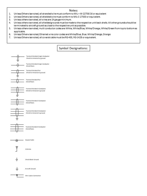
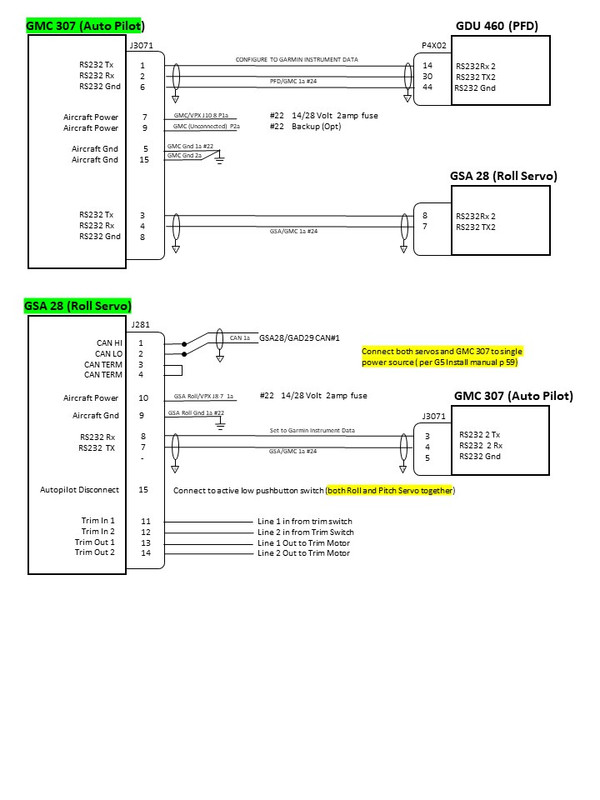
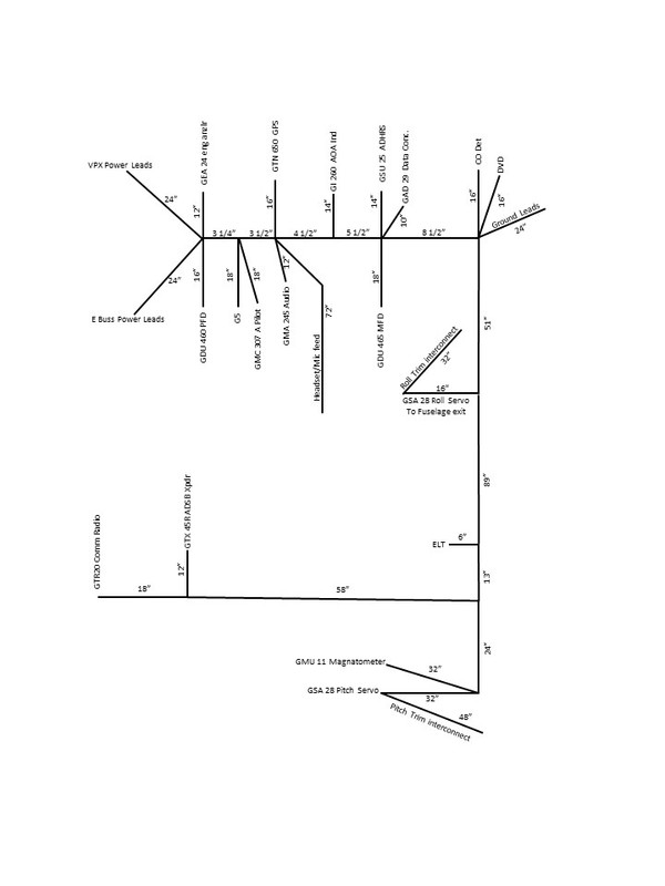
The electrical system for an aircraft can be sub-divided into sections. The first is described as the ‘Backbone’ and consists of the battery, master relay, main power (and ground) distribution, starter relay, starter and alternator(s), all the big wires. This is where the architecture of the system should first incorporate any desired redundancy (multiple batteries, alternators, E Buss, etc.). Since I have chosen to build for IFR level of function, and I plan on an electric airplane, I chose the Z13/8 (with E Buss) figure in the back of Bob Nuckolls’ book as the basis. I then modified this architecture to incorporate the VPX-pro ECB (electronic circuit breaker) system.
Here is the resulting drawing with more discussion to follow:
[IMG]  [/IMG]
The ‘backbone’ architecture:
• Two alternators 60 amp and a backup at 30 amp
• Single main battery with dedicated G5 back up battery
• I am considering an additional supplemental battery, but will add it later if needed. (primarily to maintain voltage during engine starting)
• E-Buss
• VPX electronic circuit breakers (ECB)
__________________
Building started Oct 5th 2014, Flying since 1/16/2020
http://www.mykitlog.com/leok
RV Hotel, come by and visit if you're in town
Dues paid 2023
Last edited by leok : 06-25-2018 at 03:13 PM.
|

08-11-2017, 01:58 PM
|
|
|
Join Date: Apr 2013
Location: Forest City, NC
Posts: 451
|
|
Electrical Design and Build continued
Much of the design flows out from these early choices. i.e. Choosing to use the VPX-pro as the ECB system drives many other features. Among other capabilities the VPX has 32 assignable power outputs and 10 assignable input switches. That means that any of the 32 power outputs (think circuit breakers) can be assigned to any of 10 switches (or left always on) to be switched individually or in assigned groups. Because of this capability I divided my avionics into 3 groups each addressed to one of the three switches. I can unload the avionics from electrical system stepwise in 3 quick steps or individually. I chose 3 groups, because I have 3 power levels: 1) primary alternator of 60 amps 2) backup alternator with 30 amps and 3) E Buss with 15 amps direct feed from the battery. The E Buss bypasses the VPX and master contactor and feeds directly from the battery. If the primary alternator fails, switch to BU alternator and turn off tertiary avionics. If the secondary alternator fails, turn on E Buss and turn off secondary avionics. I then have critical instruments using minimum power consumption to get me on the ground. This also works well in reverse for a phased start-up of the avionics. I have the physical switches co-located so the switching is quick and easy without hunting.
[IMG]  [/IMG]
Each of the other 7 switches feed other groups, individual high current draws such as Pitot heat, or small fuse panels that in turn feed grouped functions such as interior lighting, exterior lighting, heated seats etc.
[IMG]  [/IMG]
Each of the small fuse blocks I designed as sub-systems that are wired independently tied in only with the power feed from the VPX.
For example, I wanted rather extensive interior lighting. This comes from years of flying with the terrible lighting in certified aircraft, and many years in automotive engineering with good lighting. I have reading lights at each seating position, red and white instrument panel lights. I have RGBW (color adjustable lighting) for under glare shield lights, overhead, foot-well, switch tip and switch label back lights. All are LED and all are dimmable. These all feed from one small fuse panel controlled by one VPX switch with individual switches for each item.
[IMG]  [/IMG]
Exterior lighting is the similar with navigation, strobes, wig wag, landing, taxi and tail beacon. These are switched as a single VPX power feed, with individual switches for each item.
Boarding lights come on when the doors are opened. I have a small battery direct, un-switched feed that has an override for when the doors need to be open for extended periods. I also feed several USB charge ports (to charge a phone at Oshkosh without the master on).
__________________
Building started Oct 5th 2014, Flying since 1/16/2020
http://www.mykitlog.com/leok
RV Hotel, come by and visit if you're in town
Dues paid 2023
Last edited by leok : 06-25-2018 at 03:19 PM.
|

08-11-2017, 02:05 PM
|
|
|
Join Date: Apr 2013
Location: Forest City, NC
Posts: 451
|
|
Electrical System Design and Build continued
I control the heat vents, fore/aft and left/right with servos managed by an Arduino mini-computer. I have heated front seats
[IMG]  [/IMG]
I have roll, pitch and rudder trim with roll and pitch integrated into the Garmin autopilot and auto trim system. Both the Garmin autopilot and the VPX can provide speed scheduling for trim speed to roll and pitch.
Getting this all together was an iterative process with thoughts and ideas incorporated over time, with imagined flights, thought and study.
Designing the System – Step One
As a beginning, I made a list of all functions I wanted. This included everything from IFR flight to boarding and loading the airplane in the dark. It is important to get this as comprehensive as possible as each design step grows out of the previous. Later changes are laborious to incorporate. I did the initial step in Excel so I could move things around easily.
1) Make a list of functions
2) Separate the list into functionally related groups
• Avionics related (I subdivided into 3 groups)
• Interior lighting
• Exterior lighting
• Stuff I always want power to (door entry lights, USB charge receptacles)
• Stuff I want power to only when the Master switch is on
• Stuff I need to provide back up and/or levels of redundancy and/or emergency
From the function list, I created a list of the avionics boxes I would be needed to accomplish the various functions. Based on my list I found the total price from each supplier to be within 2 AMU. I did not find price a significant differentiator for the functionality I had worked out.
I chose Garmin because it was the only provider with a full integrated lineup. That choice was further strengthened as I learned more about the CAN communications buss and backup pathways built into the G3X system. I also wanted easy integration with one stop support. Your choices may be different based on your circumstances/priorities.
With the list of avionics, I then separated then into three groups as I have three levels of power/redundancy.
1) Items absolutely required to get me on the ground in case of with the loss of both alternators ;
• PFD
• G5
• Radio 1
• GPS/Nav source
• 1 electronic engine ignition
• ADAHR/Magnatometer
2) Items nice to have if power supplies are reduced (to be switched off when on battery only);
• MFD
• Auto Pilot
• Transponder
• Engine Monitor Module
• Roll/Pitch Servo
3) Items I could do without and continue happily on my way (to be switched off when on the smaller back up alternator);
• Radio 2
• Intercom/Audio Panel
• Rudder Trim
Grouping the functions and assigning to individual VPX switches, then organizing the physical switch locations for logic and ergonomics is an iterative process. I stepped through many flights, eyes closed, comfortable in an easy chair, to slowly refine how I wanted the ‘flow’ and ergonomics to function.
[IMG]  [/IMG]
Designing the System - Step two
The first section of the design was to complete a drawing of the ‘backbone’ or primary power distribution system. As you can see in the attached drawing, I included all or the details necessary to provide normal, back up, and emergency power distribution and the related switches. I stopped short of detailing the individual wiring loops as they are detailed in the next steps.
[IMG]  [/IMG]
I created spread sheets detailing every device that required power to operate, every switch and what current rating was needed. Using the VPX planner tool (online at the VPX web site) I assigned each power output and decided how I wanted to switch them. The switching is a key decision because the VPX has only 10 assignable switch inputs. I had more items to switch than switch inputs even after grouping the avionics into three groups. I grouped all interior lights, exterior lights, pitot heat, and seat heat to mini power busses with VPX switched power leads feeding individual small blade fuse holders. One benefit of using the VPX for switching, is that on/off switches carry only small amounts of power, so any switch rating will do.
[IMG]  [/IMG]
With everything grouped, I designed each sub-buss as an individual system. With a single VPX switch input, and single power feed from the VPX, each sub-buss was designed, wired and tested.
__________________
Building started Oct 5th 2014, Flying since 1/16/2020
http://www.mykitlog.com/leok
RV Hotel, come by and visit if you're in town
Dues paid 2023
Last edited by leok : 06-25-2018 at 03:25 PM.
Reason: fix picture links
|

08-11-2017, 02:12 PM
|
|
|
Join Date: Apr 2013
Location: Forest City, NC
Posts: 451
|
|
Electrical System Design and Build continued
I mounted all switches to small individual sub panels in functional groups. Each switch sub-panel has connectors so they can be removed and worked on the bench.
[IMG]  [/IMG]
Next comes the Avionics
Design Step 3 - Avionics
The most complex section of the electrical design is cross connecting the avionics. After identifying the avionics, the task of designing, documenting and otherwise figuring out the required connections can be overwhelming. This is where the information learned in the G3X installation class really helps. I divided this section of the design in two parts as well, communication and power feed. The following is the process I learned and followed;
Start with a ‘Communication Diagram’ of all avionics and communication paths. What needs to talk to what, and how they talk. There are examples in Section 2 of the G3X Installation Manual downloadable from the Garmin website. In my case, I chose all Garmin avionics, others would be similar but different based on their unique features. Garmin uses a CAN network, RS 232, A429 and Ethernet to communicate between boxes, depending on the specific box. Downloading the installation manual for each box, and of course, reading the technical description, will tell you what is needed.
1) For the Garmin CAN, using a simple line drawing of the aircraft, I established a diagram of the approximate locations of all avionics that use CAN to communicate. The CAN structure is a daisy chain with terminators (120 ohm resistors) at each end. Each link is numbered in turn giving an identifier for tracking purposes. We learned in our class that for Garmin, using the GSA28 autopilot servos as the termination of the CAN is useful as the termination function is built into the device and needs only a jumper.
My CAN chain is as follows:
CAN BUS order
GSA28—GAD29—GSU25—GEA24---GDU460---G5---GDU465---GI260---GMA245---GTR20---GMU11---GSA28
2) Make a box diagram showing each device (Garmin calls these LRUs or Line Replaceable Units) in the CAN network and connect them with a line. Then review the installation manual for each component and determine what else it needs to talk to, or what needs to talk to it, and by what method. You will also need to add several boxes that do not use the CAN network. Most components will use RS232 in addition to or instead of CAN. The GTN650 GPS/Navigator/Com uses a combination of RS232, A429 and Ethernet depending on what it is talking to. Pay attention to how many ports of each type are available for each device (i.e. the GDU460 has 5 RS232 ports). For some boxes several methods are used for redundancy. This info is in the G3X installation manual for Garmin components. Each of these is added to the Communication Diagram.
With the CAN order and the communication diagram complete the ‘pin out’ diagrams can begin. This is where good preparation pays as fixing/changing earlier work takes time to alter the underlying documentation. This is also where the power and ground for each device will get added.
__________________
Building started Oct 5th 2014, Flying since 1/16/2020
http://www.mykitlog.com/leok
RV Hotel, come by and visit if you're in town
Dues paid 2023
Last edited by leok : 06-25-2018 at 03:31 PM.
Reason: fix picture links
|

08-11-2017, 02:18 PM
|
|
|
Join Date: Apr 2013
Location: Forest City, NC
Posts: 451
|
|
Electrical System Design and Build continued
Power Point is my program of choice. The instructor recommended PowerPoint in the G3X install course I took. It offers many benefits, not the least of which I am familiar and comfortable with it and have it on my computer. Others have recommended Viseo. I don’t have it, and am not familiar with it, so have no recommendation. AutoCad or other CAD software can be used if you are proficient.
As far as Power Point, almost any shape can be created out of the building blocks provided. Multiple shapes can be grouped together to move, copy and paste. Blocks can be built up to cover power, ground, RS232 connections etc. Blocks can be moved and rotated to any position on the page(s).
This is a typical pin out drawing for my PFD;
Start by drawing representations on the left side of the page for each avionics box with each connector included. I started with one page for each box, then added or combined as needed. You can see that power feed from the VPX is included in each device diagram. Refer to the sample interconnect drawings in the G3X manual for examples. Use the Garmin G3X manual interconnect drawings towards the end of the manual for examples when available for connecting specific boxes.
Wire Numbering; some conventions
When doing drawings each wire needs to be labeled. Any reasonable method is acceptable, so long as each wire can be identified. I chose to number my wires by labeled shrink tube. I purchased my shrink tube labeler for $100 on eBay. The shrink tube is needed anyway to close out the shield termination. I identify the wire by origin/end, wire number between the two devices, and segment number … This is how that looks:
GTN/PFD 1a … this equals … 1st wire from the GTN650 to the GDU470 PFD , segment #a
If it goes through a connector it would have a second segment and be GTN/PDF 1b
And if a second wire ran from the GTN to PDF it would be GTN/PDF 2a etc..
For multi conductor wires, they get one number and are connected as follows;
• A single wire is white
• 2 conductor wires are, white, white/blue
• 3 conductor wires are, white, white/blue, white/orange
• 4 conductor wires are, white, white/blue, white/orange, white/green
Wire connections always follow that order from top to bottom in multi-conductor connections so each individual conductor does not need to be called out. i.e. the first pin identified in the drawing connects to white. Second pin identified connects to white/blue, etc..
This convention as well as all symbols are identified in a definitions sheet at the beginning of the wiring diagrams.
Shield terminations are detailed extensively in the installation manuals and follow the general rules
• Signal connections terminate the shield at both ends
• Audio connections terminate the shield at only one end
Pin Out Drawings
Make a diagram for each piece of avionics. This would include each device with each(all) connector(s) for that device shown on the left side of the page. Each connection is shown as lines (one line per conductor) drawn to the right side of the page with the pins, connector number and devices identified. Each wire/multi-conductor is identified by a unique ‘number’ as described above. Like double entry accounting, the page for the connected device then gets an entry with the information reversed (left/right) and the same wire number.
To confirm each device has the correct and needed connections, confirm all communication connections in the ‘communication diagram’ have been made. Then walk through the pin out diagrams in the manuals checking each pin function and number. I walked through the pin out of each device several times to make sure that each pin is connected as needed and confirming proper pin numbering before I stopped finding mistakes. I typed questions on each page, and called Garmin G3X customer support for answers. It took several times through the steps to get everything connected and cross checked.
__________________
Building started Oct 5th 2014, Flying since 1/16/2020
http://www.mykitlog.com/leok
RV Hotel, come by and visit if you're in town
Dues paid 2023
Last edited by leok : 06-25-2018 at 03:35 PM.
Reason: correct left/right, go figure
|

08-11-2017, 02:29 PM
|
|
|
Join Date: Apr 2013
Location: Forest City, NC
Posts: 451
|
|
Electrical System Design and Build continued
Wire Harness Fabrication
Using the diagrams and lists compiled I made full size foam replicas of each instrument and placed them with double stick tape in the plane where I wanted to mount them. I was particularly careful to place them where I could access the connectors for maintenance and there were no interferences.
I taped a flat ribbon to each box and along the routing I had determined for the main wire harness. I made sure each branch to an avionics box had a service loop as needed. Once completed, I removed, measured and made a diagram of the wire harness.
I used blue tape to lay out the harness on my work table. I placed a nail at each junction and corner to create the entire wire harness diagram in full scale. Next using spring clamps to hold the wire ends, I laid each wire from the pin out diagrams in place. I used blue tape to temporarily label both ends of each wire.
VERY IMPORTANT for a nice clean job… Once all wires are in place, lace the wires starting at the main trunk and working out each branch. The wires will move as they are laced. You only want to trim the ends to the same length once after everything is laced nice and tight. Lacing knots are available in several locations, so I will not cover them here.
__________________
Building started Oct 5th 2014, Flying since 1/16/2020
http://www.mykitlog.com/leok
RV Hotel, come by and visit if you're in town
Dues paid 2023
Last edited by leok : 06-25-2018 at 03:47 PM.
Reason: Fix pic links
|

08-11-2017, 02:32 PM
|
|
|
Join Date: Apr 2013
Location: Forest City, NC
Posts: 451
|
|
Electrical System Design and Build continued
Shield Termination, CAN splices and Connectors
To terminate the shields, strip off about 3-4 inches of the outer cover. Push back the shield wire forming a mushroom head about ½ inch from the remaining outer cover. Clip off the mushroom head and remove the shield. Striping back about ¾ inch of 22 gage hook up wire, fan the end and wrap around the remaining exposed shield. Solder the joint then slip a printed piece of shrink tubing, and shrink in place. The shrink tubing completes the shield termination and provides a label for each wire if you use printed shrink tubing.
The finished shield termination
For the CAN splices we were taught window splicing. I terminated the shields of the CAN leads with about ¾ inch longer leads than the other wires. Use the wire stripper to open about ¼-3/8 inch of each conductor on the CAN leads to each device. White to white and blue to blue. Cut off one lead, fan the wires, and wrap the end around the window on the other wire. Solder, shrink tube each splice and then shrink tube both leads up to the shield termination for strength. This leaves about 2-3 inches of wire to feed into the connectors.
Here is what one of the bundles looks like before adding the connectors
And lastly, where I did not need to feed the wires through conduit or bulkheads, the connectors were added per Garmin instructions.

__________________
Building started Oct 5th 2014, Flying since 1/16/2020
http://www.mykitlog.com/leok
RV Hotel, come by and visit if you're in town
Dues paid 2023
Last edited by leok : 06-25-2018 at 04:06 PM.
Reason: Fix pic links and add a few photos
|

08-11-2017, 02:48 PM
|
|
|
Join Date: Nov 2010
Location: Boston Area
Posts: 136
|
|
What happens is the VPX dies?
Tim
|

08-11-2017, 04:33 PM
|
 |
|
|
Join Date: Aug 2016
Location: Asheville, NC
Posts: 2,122
|
|
I like how you approached this problem. Your diagrams were excellent! You must have been an engineer on the Space Shuttle program 
__________________
(2020 dues paid)
|

08-11-2017, 06:58 PM
|
|
|
Join Date: Apr 2013
Location: Forest City, NC
Posts: 451
|
|
Quote:
Originally Posted by tspear
What happens is the VPX dies?
Tim
|
The E Buss bypasses the Master Relay and the VPX. Switch the E Buss on and the flight critical components are powered direct from the battery
__________________
Building started Oct 5th 2014, Flying since 1/16/2020
http://www.mykitlog.com/leok
RV Hotel, come by and visit if you're in town
Dues paid 2023
|
Thread Tools |
Search this Thread |
|
|
Display Modes |
Linear Mode
|
Posting Rules
|
You may not post new threads
You may not post replies
You may not post attachments
You may not edit your posts
HTML code is Off
|
|
|
All times are GMT -6. The time now is 04:06 PM.
|