What's new
Van's Air Force

Don't miss anything! Register now for full access to the definitive RV support community.

starter current and ammeter shunt

dmn056

Well Known Member
Friend
I have a SkyTec starter. Their website says typical current requirements are 190A initial inrush and 65-90A continuous.

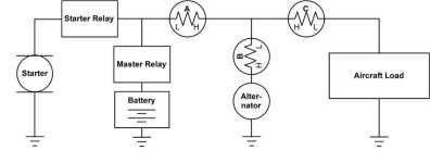
I'm thinking about using a Dynon 0-60A ammeter shunt for current measurement, putting it on the battery negative lead. The Dynon Skyview installation manual just says to not install the shunt on the starter cable, but it seems to me (a non-electrical expert) that anywhere in the battery circuit will experience the same current flow.

I've done a search on the Dynon forum without finding much about this.

Does anyone know if the Dynon shunt and the Dynon EMS220 system it connects to will tolerate these starter loads?

Thanks for your help.
 
The Dynon shunt must go on a positive lead and not on the battery negative cable. It is not designed to carry the starter current.
The Skyview installation provides three recommended locations for the shunt, depending on whether you want to measure current from alternator, or current from battery to the bus, or combination of the two. There is a diagram for this in the manual.
 
Shunt

The Dynon shunt must go on a positive lead and not on the battery negative cable. It is not designed to carry the starter current.
The Skyview installation provides three recommended locations for the shunt, depending on whether you want to measure current from alternator, or current from battery to the bus, or combination of the two. There is a diagram for this in the manual.

The preferred location is as mentioned but they do prefer one of the three choices. I called tech support.
Location "A".

This way the system will read all amps flowing either way.
 
Does anyone know if the Dynon shunt and the Dynon EMS220 system it connects to will tolerate these starter loads?

Thanks for your help.

So, what are you missing here? Starter draws around 200 amps and the shunt is rated at 60 amps. Kind of a no brainer that running starter current through the shunt is going to over load it. Never tried doing it, so couldn't tell you whether it will blow up your EMS, snap the shunt, or start a fire, or some other bad thing. However, all seem undesirable. You should assume the rating is there for a reason.

Putting the shunt on the Neg cable off the battery is going to see starter current. It needs to go on Pos side, downstream of where you tap off the master contactor for the internal bus feed. Given the questions here, suggest either following the Vans diagram or find someone knowledgeable to help lay it out on paper.
 
Last edited:
The shunt can be damaged by starter current. Do NOT install the shunt in the battery negative cable because it carries starter current. The attached picture from the Dynon manual shows some possible locations. I do NOT recommend position "C". Locations A and B are a matter of personal choice. I prefer "B". You might consider using a Hall Effect Sensor instead of a shunt.
 

Attachments

  • Shunt.jpg
    Shunt.jpg
    29.4 KB · Views: 94
I have never heard of it but I think you could have a shunt made to put inline on the starter cable.. a call to Electronics International will get you an answer, I use one of there volt ammeters, the shunt just takes a very small fraction of the voltage passing through the shunt and converts it to current. Your 60amp shunt would melt after a period of time putting 200 amps accross it, at least get very hot.. the ammeter wires would catch fire or blow the fuse
 
I have never heard of it but I think you could have a shunt made to put inline on the starter cable.. a call to Electronics International will get you an answer, I use one of there volt ammeters, the shunt just takes a very small fraction of the voltage passing through the shunt and converts it to current. Your 60amp shunt would melt after a period of time putting 200 amps accross it, at least get very hot.. the ammeter wires would catch fire or blow the fuse

The current is calculated from the known resistance of the device (shunt) and resulting change in potential across it associated with current. As the amp meter and associated instrument wiring is really only measuring (milli)volts, it's unlikely to be a fire hazard.
 
Well if he put his 60 amp shunt inline with the starter like I said in my post... its not meant for 200 amps and will melt in two, and the millivolt wires being 22 gauge or maybe 18 at most will get pretty hot and melt to. I have melted a 50 amp shunt before accidently, shorted the battery by grounding the alternator output cable .. long story, they break just like a fuse, but you might be right it may not catch fire, but will melt something and fast
 
Last edited:
I don't understand why the OP, who admits to not being familiar with electrical engineering, would want to NOT do what the installation manual from the manufacturer says TO do.

Just put it in one of the three places THE MANUFACTURER recommends, understand why you picked a particular one of the three, and *quit tempting fate*.

Improperly installing the ammeter shunt can result in high current flow, electrical system failure, or fire.
- Dynon SV Installation Manual
 
Last edited:
Keep in mind that no shunt is required. For our applications voltage is a very good indication of power generation system health.

I measure aircraft current draw after completion using a bench power supply. The data verifies the install and provides reference for POH electrical system backup modes. 20 years and three builds and all is well. I never liked adding big clunky terminals and connectors on the firewall.

But - if you must have continuous current readout consider a Hall effect pickup instead: https://grtavionics.com/product-category/eis-probes/current-sensors/j

Although sold by GrandRapids, at least the Dynon SkyView install talks about how to use it with their EMS module.

Carl
 
Last edited:
Per the manual

Installed mine per the manual and it’s worked for 6 years. Do it another way and it’ll work for about 10 seconds. Then u get to see smoke.
 
Keep in mind that no shunt is required. For our applications voltage is a very good indication of power generation system health.

Neither is a voltmeter required, but it's nice to have. So is an ammeter.

Lots of things aren't required, but certainly are helpful. EGT, CHT...the list goes on and on.
 
Thank you all for your comments.

To explain why I am looking for an alternative to the Dynon manual's Figure 83 recommendations, I'm planning a dual battery, dual alternator, single main bus system and I want to monitor the batteries individually. This makes it difficult to find a shunt location which doesn't include starter loads.

It's the starter inrush current which bothers me, but since it is typically only for milliseconds duration I was hoping someone might tell me that the Dynon shunt 60A rating was for continuous loads and that it would tolerate much more than that for a very short duration.

A sort of justification for this is in the OEM documentation for FL-21 shunts, which Dynon sell. They describe it as tolerant of overload, specifying 120% of rated load for two hours. By my calculations, this represents about 31 kJ, ignoring thermal dissipation. Applying the 190A inrush current for an extremely conservative 30 sec, I calculate about 1.1 kJ. It seemed to me this might mean that the shunt could easily tolerate the starter loads, as long as they weren't applied too frequently.

However, I guess I'll have to look for an alternative layout, or an alternative sensor.

Thanks again to VAF.
 
Last edited:
Did you call EI, making the ammeter is no problem. Bigger shunt and calibrated correctly its simple, at least it sounds easy to me. You can always run your dycrap ammeter the way they recommend but I would never pay money for their junk after the experience I had with them over a defective item they refused to honor the warrenty.
 
Your shunt might handle the current, but if it blows than you are going to have hundreds of amps rerouting thru the small wires to your ammeter, thats when you will start melting things and could catch fire.

If all youre intrested in is battery current than why not have a shunt on each battery?

Im not sure your reasons for setting up 2 batteries 2 alternators and a single bus the way you want. I would have one battery as a backup on a switch and alternate batteries every other flight, with 2 batteries I would not have two alternators.
 
Last edited:
Your shunt might handle the current, but if it blows than you are going to have hundreds of amps rerouting thru the small wires to your ammeter, thats when you will start melting things and could catch fire.

Yes, Dynon recommends a 1A fuse on each wire to the EMS220 shunt inputs for that reason.

If all youre intrested in is battery current than why not have a shunt on each battery?

Yes, that's what I was planning.
 
Might or might not handle start currunt. I would not try starting through a 60 amp shunt.
 

Attachments

  • Screenshot_20230608-202857_Gallery.jpg
    Screenshot_20230608-202857_Gallery.jpg
    291.3 KB · Views: 33
There are alternatives to Dynon for measuring higher currents, e.g. the EI ammeter is available with a shunt up to 300A, if that is the requirement.

Another way to monitor two batteries with the Dynon EMS is to make use of the two voltmeter inputs with one connected to each battery +ve lead (and appropriate fusing to protect the wires). I find it helpful to know the battery voltage(s) with and without the engine running.
 
Thank you all for your comments.

To explain why I am looking for an alternative to the Dynon manual's Figure 83 recommendations, I'm planning a dual battery, dual alternator, single main bus system and I want to monitor the batteries individually. This makes it difficult to find a shunt location which doesn't include starter loads.

It's the starter inrush current which bothers me, but since it is typically only for milliseconds duration I was hoping someone might tell me that the Dynon shunt 60A rating was for continuous loads and that it would tolerate much more than that for a very short duration.

A sort of justification for this is in the OEM documentation for FL-21 shunts, which Dynon sell. They describe it as tolerant of overload, specifying 120% of rated load for two hours. By my calculations, this represents about 31 kJ, ignoring thermal dissipation. Applying the 190A inrush current for an extremely conservative 30 sec, I calculate about 1.1 kJ. It seemed to me this might mean that the shunt could easily tolerate the starter loads, as long as they weren't applied too frequently.

However, I guess I'll have to look for an alternative layout, or an alternative sensor.

Thanks again to VAF.

My last post on this. You really need to get off this idea. There are several things that can cause that starter to draw more current than what you are posting. What if 4 years down the road you forget about the back alley engineering and have a starter problem and you mechanic throws on an old remy starter to diagnose and it pull 300 amps? If you were talking about running 70-80 amps through a 60A rated device, I might say "ok, probably some fudge in there," but we are talking about 100's of amps on devices that are known to get very hot and start fires when their rated capacity is exceeded. I feel it is insanity to tempt fate here with little benefit to be gained. WIll include the disclaimer that this is your plane and you can build it however you want. Just don't ask me to fly in it.

Possibly you have a friend who is an electrician. Maybe ask him how he would feel about running 3X the electrical load through a breaker, switch, wire, etc. A good question for him. "I have a 15 amp circuit in my home and want to put a space heater on it. It will normally run at 17-18 amps but occasionally will run at 45 amps for a few seconds." see what he says.

a hall effect sensor has been suggested several times. They create no risk when overloading. Suggest moving in that direction.

Larry
 
Last edited:
I dont understand the whole two alternators thing, especially with two batteries. Why not buy yourself an extra alternator and carry it in a flyaway kit with a couple wrenches to swap it out IF you ever have it go bad on the road...

The other thing I am not even going to try and understand is the dual battery setup wired together... Tim Taylor would not even do this, but if you do it why not go all out and wire 3 or 4 or 5, lets really get some power in there. I could see having an extra back up battery installed but have it switchable and not running together at the same time, switch batteries every other flight. Or carry a backup battery with you in the baggage compartment.

I suggest a study of two battery schemes would help you understand how they can provide the redundancy needed to mitigate risk of most practical single point failures. Some schemes are better than others so look at more than one.

I run two PC-625 batteries in parallel for normal operation. When there is a fault they get split out, each feeding half the panel. This is the only immediate pilot action for any electrical issue. Multiple backup modes provide for full panel recovery after this immediate action. Such backup modes are not possible with the 1960 Cessna style single battery power distribution.

Assuming the alternator(s) is the only thing that can fail is not how I would ever fly IFR.

Carl
 
Im interested, expand a bit on the types of failures where this setup helps, guess I have been fortunate over the years and not experienced any electrical failures other than the ones I created myself while at home airport working on my plane.
 
Thank you all for your comments.

I've now talked with a couple of electrical engineers, who also feel that a shunt exposed to starter currents is a bad idea. They are helping me lay out a system which will safely provide the information I'm looking for, based on Hall effect sensors chosen to match the expected current ranges.

I guess it's all part of my learning experience.
 
I suggest a study of two battery schemes would help you understand how they can provide the redundancy needed to mitigate risk of most practical single point failures. Some schemes are better than others so look at more than one.

I run two PC-625 batteries in parallel for normal operation. When there is a fault they get split out, each feeding half the panel. This is the only immediate pilot action for any electrical issue. Multiple backup modes provide for full panel recovery after this immediate action. Such backup modes are not possible with the 1960 Cessna style single battery power distribution.

Assuming the alternator(s) is the only thing that can fail is not how I would ever fly IFR.

Carl

I wired my GNC 355 and GRT Mini GA with a removable backup AA battery pack quick disconnect that isolates the GNC 355, King 209 and GRT Mini EFIS from the rest of the electrical system in case I ever had to turn the battery master off, I carry 16 AA batteries should get me through 10 hours of flight with light radio use.
 

Attachments

  • 20230609_115022.png
    20230609_115022.png
    326.9 KB · Views: 26
Last edited:
I wired my GNC 355 and GRT Mini GA with a removable backup AA battery pack quick disconnect that isolates the GNC 355, King 209 and GRT Mini EFIS from the rest of the electrical system in case I ever had to turn the battery master off, I carry 16 AA batteries should get me through 10 hours of flight with light radio use.

A string of 8 AA Alkaline batteries will provide around 12V @ 2 amp hours (std batteries less than 1/2 that). Near the end of capacity, it will be down to 9.6 and therefore the Amps drawn increases (wattage need), if the equip will even run on 9.6. Mini and 355 probably pull close to 2 amps total @ 12V and probably 5-7 amps during transmit. Not sure I follow your math for 10 hours of backup. Never studied alakaline tech, but guessing that at 7 amps, the capacity drops WELL below 2 Ah (do know that with lead acid, Ah rating drops significantly with draws above 1C). A pc680, eventhough rated at 16 Ah, will only provide for 1 hour of use at 10-11 amps of draw because the Ah rating is set at a low draw by the markeitng guys to sell more batteries. It is a clever idea, but you are kidding yourself to think it will last 10 hours.
 
Last edited:
A string of 8 AA Alkaline batteries will provide around 12V @ 2 amp hours (std batteries less than 1/2 that). Near the end of capacity, it will be down to 9.6 and therefore the Amps drawn increases (wattage need), if the equip will even run on 9.6. Mini and 355 probably pull close to 2 amps total @ 12V and probably 5-7 amps during transmit. Not sure I follow your math for 10 hours of backup. Never studied alakaline tech, but guessing that at 7 amps, the capacity drops WELL below 2 Ah (do know that with lead acid, Ah rating drops significantly with draws above 1C). A pc680, eventhough rated at 16 Ah, will only provide for 1 hour of use at 10-11 amps of draw because the Ah rating is set at a low draw by the markeitng guys to sell more batteries. It is a clever idea, but you are kidding yourself to think it will last 10 hours.


Guess I need to carry C cells or D. C are rated at 8ah and D 12ah. Thr GRT says 2amps hour, and the 355 is about the same, xmitting will increase the draw but I have powered my a22 for two days transmitting qiute a bit on 8 AA batteries.. Total about 5 minutes total xmitt time I guess, maybe 3 minutes total, but the AA 8 pack lasted all weekend flying a Cub without elecetrical system.
 
Last edited:
Battery pack

Guess I need to carry C cells or D. C are rated at 8ah and D 12ah. Thr GRT says 2amps hour, and the 355 is about the same, xmitting will increase the draw but I have powered my a22 for two days transmitting qiute a bit on 8 AA batteries.. Total about 5 minutes total xmitt time I guess, maybe 3 minutes total, but the AA 8 pack lasted all weekend flying a Cub without elecetrical system.

You could add one of these 8-cell, with an appropriate connector (usb or lighter plug) to back feed the panel. Flip off the master and plug in the battery pack.
Just a wild thought.
 
Last edited:
Back
Top