What's new
Van's Air Force

Don't miss anything! Register now for full access to the definitive RV support community.

NEW! Ultimate C/S Prop Wrench Anti Splat Aero

Bravo Mike!!!!
This is the best post so far!

Actually the best post so far Allan is the first post of this thread where you offer this wonderful tool to those of us who have fought the battle too many times taking a C/S prop on and off.
 
Larry is raising an interesting point....

In Larry's defense, the question he is asking, specifically about the behavior of a click-type torque wrench, is worth pursuing.
This is entirely separate from the whole statics issues of the resulting torque obtained at the bolt using an extension. (A discussion which I have excercised an uncharacteristic level of impulse control in not wading into...plenty of others have done a good job there, including my good friend Bob Kuykendall)

The question is this:

Does a click-type torque wrench actually measure the true moment at the head of the wrench, or, does it do this approximately by responding to the combination of moment and shear force at the head that results from pulling at the nominal handle end?

Evidence that suggests that it does respond only to the moment:
The fact that click-type torque wrenches do not use a teetering handle to fix the point of application suggests that one benefit of click-type torque wrenches is that they are at least somewhat insensitive to the point of application of the force, and therefore insensitive to the shear force at the head of the wrench. So, if you grab it an inch or two away from the nominal handle posittion, it shouldn't affect the torque.

But.....

Is the internal design of the wrench such that this is REALLY true, or only approximately true? If we double the length of the handle with a cheater, and thus cut in half the shear force at the wrench head, does the wrench REALLY still click at exactly the right torque, or does it click at a somewhat different torque because it is influenced by the shear force and moment in combination?

Evidence that suggests that it may respond to a combination of moment and shear:
Looking at the outside of a click-type wrench and imagining what is inside, it appears there is some kind of pivot point a finite distance away from the actual wrench head, and the part that the head is attached to must move when the part snaps past a sear or cam that is spring loaded to a certain force. So, the fact that this pivot is a finite distance away from the wrench head means that it is really only at that pivot that a pure moment is measured. The moment change from the pivot to the head is dependent on the ratio of the distance from the pivot to the head and the distance from the pivot to the handle. Since the pivot is much closer to the head, the moment gradient (from the shear force) doesn't cause much change in moment between the two points....but it would cause SOME change. So, for large changes in handle length (and thus large changes in shear force) there would be a significant change in the wrench calibration, i.e. it would click at the wrong torque at the head.

Honestly, I don't know the answer to this. I think a lot of us have assumed that it must respond purely and only to the torque, or it wouldn't be a very good concept for a torque wrench. But, as Larry is trying to get to, the devil is in the details. What is the internal design such that it would have no sensitivity at all to the shear force at the wrench head?

This would be an easy test to do with two torque wrenches. No need to weld anything, just find a 12-point socket that fits the drive lug of the second wrench. Do they both click at the same time when both are pulled on their intended handles? If so, do they also both click at the same time if one is pulled at its intended point and the other pulled from a long cheater bar? Or, just compare a clicker to a beam type wrench.
 
Last edited:
Explanation With The Math

Good...

Because I'm aware of everything you just said. But, it doesn't explain, what I'm looking for.

I've spent the last two days, scouring the Internet for the exact info I want. I've linked to numerous calculators. I don't need to hear anymore ...re quoting of the same numbers.

OK Larry, You are correct and I feel like it is time to explain this with the true numbers and set everyone's mind at ease. This discussion has been absolutely wonderful for us and since Sunday PM we have sold all but nine from our first run of 400 wrenches. Thank you to everyone for your support.
So here goes! First lets get the numbers established we are working with. To make this easier we will use 100 ft lb as the called out torque (ft lb is based at 12"). So 12" = 100% without our wrench. Our prop wrench is exactly 3" center distance. You take the 12" divided by 3" = 4 times or 25%. Now you add the 12"+3"=15" or 125% with no correction you would be over torquing to 125 ft lb with our adapter. So you must divide the 100 ft lb call out by 1.25. 100 / 1.25 =80.
thus the .8 multiplier. Using a 3" adapter you must set your ft lb torque devise (what ever it may be) to 80 ft lb to achieve 100 ft lb at the bolt. This is the math and nothing will change this fact. I hope I haven't offended anyone by presenting this in it's simplest form. I just want to clarify this to everyone. Love this forum and all who use it. Allan
.
PS Keep an eye on our web site as we will be introducing several new products in the coming weeks.
.
 
How are the halves bonded together?

Ultimate C/S Prop Wrench
We have completed our testing and development on this product and now are offering them for sale. Please have a look at the demonstration video below. If you have a constant speed propeller or work on airplanes you will definitely want one of these. Let us know your opinions. Regards all, Allan
.
http://antisplataero.com/Videos.html
.
http://antisplataero.com/Products.html

The wrench appears to be made from two pieces bonded together to double the thickness... how are the two halves bonded together?
 
One more try:eek:

I will use the same 100 #/ft as before to keep the math easy

Torque is properly expressed as "pounds force foot", not "foot pounds"

It does not matter is the torque is generated by by a hundred pounds of force on a one foot lever arm, or a fifty pound force on a two foot arm or a one pound force on a hundred foot arm, or two hundred pounds of force on a half foot arm, it will all equal a torque of 100 pounds force foot.

Remember torque and force are not the same thing.

Torque is a form of force, as related to moving something around a center.

Force is a straight line effort to move something.

Going back to the problem at hand, the end point of whatever kind, or size of torque wrench is seeing a torque of 100 pound force feet. It does not matter what kind or size wrench generated this torque, or if it was even a wrench---could be an electric motor, a spring, or pixies dancing on a toothpick, just forget about how the torque is created. If we add an extension of .three inches (25 foot) to the arm, what does that do to the to the torque????

It is no longer 100 pounds force foot, it is now 125 pounds force foot, at the end of the added arm.

To get the torque back to our target of 100 pounds force foot, we need to reduce the force side of the equation by 100/125, or .8.

All the diagrams with pivot points and such are not showing torque, they are showing force-------they are lever diagrams.

At least that is how I see things, YMMV.

Like you-know-who always says, my $0.02

And yes, it is a pretty strong toothpick.
 
Last edited:
The wrench appears to be made from two pieces bonded together to double the thickness... how are the two halves bonded together?

You are correct! They are laminated together and plug welded two places in the beam. This is done to give it extra strength as the grain structure is omnidirectional and the heat treating processes are done before the two are joined together.This process also enables us to hold much tighter tolerances with our laser cutter due to the thinner material. Thanks, Allan
 
Ok one more

Here's a video I just made answering one of the questions that I think Larry was asking and Steve clarified. Does it matter where you hold a clicker type torque wrench. Intuitively you would think it shouldn't matter much. But as you can see using a Snap-On 100 ft-lbs clicker torque wrench set to 25 ft-lbs (300 in-lbs) and pushing against a Snap-On 600 in-lbs dial torque wrench, there is a significant error when pushing in the middle of the wrench instead of the handle. I don't know exactly how the mechanism works but I know it's calibrated using the handle.

http://youtu.be/_1LZk0jnQrA

By the way, this clicker wrench just happens to have an effective length of 12 inches so it should work perfectly with Allan's wrench and a .8 multiplier.

Yes, you should always use all torque wrenches as designed. With our tool you need the .8 multiplier, always. Please read my post #203.Thanks, Allan
 
OOPS

I just realized my last post left out a bit of information that may be caught by some of the sharp eyed folks here ...........

When the 3" tool is added, the rotational point is displaced a bit, and will probably cause a very minor error to be induced into the formula.

Probably some global pi r cubed thing, factored at arc sine zero, or thereabouts.

Any math majors out there want to clarify???
 
Allan, your math is incomplete

I'd like to suggest that you should really open your mind to the possibility that you are seeing this incompletely and have something to learn from the several educated sources here that are trying to help.

Look what happens to your math if we agree to use metric units for your equation? Nature doesn't know anything about measurement units. There's nothing magic about a 1 ft length basis for a torque measurement.
What if we use Newton-Meters? Your extenstion wrench is 7.6% of a meter long. So why wouldn't the torque increase be 1.076?

What is missing from your math is the added torque from the shear force at the head of the wrench acting over the length of the extension. Study Bob Kuykendall's figures, or the figures in AC43.13. They are correct.

This is more than an academic arguement because people need to be able to use your great product in a way that insures that they are safe.

By the way, we have far exceeded the expected number of posts for Goodwin's Law to kick in. I applaud everyone's patience.

OK Larry, You are correct and I feel like it is time to explain this with the true numbers and set everyone's mind at ease. This discussion has been absolutely wonderful for us and since Sunday PM we have sold all but nine from our first run of 400 wrenches. Thank you to everyone for your support.
So here goes! First lets get the numbers established we are working with. To make this easier we will use 100 ft lb as the called out torque (ft lb is based at 12"). So 12" = 100% without our wrench. Our prop wrench is exactly 3" center distance. You take the 12" divided by 3" = 4 times or 25%. Now you add the 12"+3"=15" or 125% with no correction you would be over torquing to 125 ft lb with our adapter. So you must divide the 100 ft lb call out by 1.25. 100 / 1.25 =80.
thus the .8 multiplier. Using a 3" adapter you must set your ft lb torque devise (what ever it may be) to 80 ft lb to achieve 100 ft lb at the bolt. This is the math and nothing will change this fact. I hope I haven't offended anyone by presenting this in it's simplest form. I just want to clarify this to everyone. Love this forum and all who use it. Allan
.
PS Keep an eye on our web site as we will be introducing several new products in the coming weeks.
.
 
Size doesn't matter

In this exercise, and possibly only this one! The size of your tool means absolutely nothing. It's all in the size of my tool and the way you use it.:rolleyes::rolleyes::rolleyes:
 
I think it's time for a poll:D

By the way, I find it very interesting that the issue of torque wrench extension correction factor turned out to be so controversial, like primer or no primer, tailwheel vs. nosewheel, tipup vs. slider, etc., because in this case there IS only ONE truly correct answer and it can be (and has been) PROVEN mathematically.

This is not rocket science, but at least one rocket scientist, scsmith, along with many, many other very informed individuals have weighed in with the correct answer. The correction factor is NOT constant, but dependant on the length of your torque wrench (as measured from the center of the socket stud to the center of the handle), the length of the extension, and the angle of the extension.

If you are torquing your prop bolts with this tool or any other torque wrench extension tool (Avery's, Hartzell's, crow's foot, etc.), ALWAYS follow the instructions in AC-43.13 and the torque values for your propeller.
 
Last edited:
...This discussion has been absolutely wonderful for us and since Sunday PM we have sold all but nine from our first run of 400 wrenches. Thank you to everyone for your support...

Allan, your explanation is still invalid, your math is still wrong, and the torque values that follow from them are dangerously under-spec for any torque wrench with a handle longer than about 18". Several engineers, both mechanical and aeronautic, have clearly explained why that is so.

The fact that you so cavalierly exploit the controversy you have stirred up here to increase sales suggests that you do not have your customers' best interests at heart. I hope that that is not actually the case.

Thanks, Bob K.

Bob; My explanation is absolutely valid, my math is perfect and the torque values that follow from them are spot on. I graduated top of my class at MIT with three degrees in mechanical engineering with specialties in stress analysis and metallurgy. I have over forty years experience in tool design, owned and operated Omega Tool Co. (A company with 6 m $ yearly revenue specializing in the development and manufacture of specialized aircraft tooling). Believe me when I say, "I do not make mistakes with Jr High math". As for your accusation that I have somehow stirred up a controversy, down rite ridiculous! I posted a top of the line product at a very low price with clear, concise instruction in it's use. The controversy was generated by the very small camp that has a problem understanding this simple mechanical concept. They passed their confusion on to others who truly wish to understand. I will rectify this misconception early next week when I return from my business trip on Tuesday the 21st. Keep an eye out for the video as it will be very entertaining as well as informative. Thanks,Allan
 
Two More Videos

Okay, Here are 2 more videos that hopefully show once and for all that statics works and that the equation Wrench Torque = Bolt Torque (wrench length) / (wrench length + crows foot length) is correct. All I had was a 1 inch crows foot with a 1.5 inch offset. The clicker torque wrench is 12 inches and the cheater is 20 inches.

I'm no Allan when it comes to making videos. Sorry about the volume (turn it all the way up). The Drift HD mic didn't pic up my voice very well. Turn down the volume before the video ends because there is a nasty beep at the end of each video.

http://www.youtube.com/watch?v=sdDNYh-AxIs&feature=channel

http://www.youtube.com/watch?v=nNjyef_3vvQ&feature=channel
 
Bob; My explanation is absolutely valid, my math is perfect and the torque values that follow from them are spot on. I graduated top of my class at MIT with three degrees in mechanical engineering with specialties in stress analysis and metallurgy. I have over forty years experience in tool design, owned and operated Omega Tool Co. (A company with 6 m $ yearly revenue specializing in the development and manufacture of specialized aircraft tooling). Believe me when I say, "I do not make mistakes with Jr High math".

No one is arguing that your math is wrong. The problem is in one of your assumptions. Specifically, your claim that you can insert 12" arbitrarily into the equation simply because you are using ft -lbs as your unit of measure. If you convert YOUR math to the metric system with YOUR assumptions you will get a different multiplier, because you will be putting 100cm in place of your 12" (assuming you use N-m as your torque measurement) since 100cm = 1m.

As for your accusation that I have somehow stirred up a controversy, down rite ridiculous! I posted a top of the line product at a very low price with clear, concise instruction in it's use. The controversy was generated by the very small camp that has a problem understanding this simple mechanical concept. They passed their confusion on to others who truly wish to understand. I will rectify this misconception early next week when I return from my business trip on Tuesday the 21st. Keep an eye out for the video as it will be very entertaining as well as informative. Thanks,Allan

If this were in fact a primer war I'd have gotten out of it long ago. But this is prop torque. I don't want to read this in some NTSB report two years from now and know that there was 'something else' that I could have said.

Let's summarize ....

Side A claims that 0.8 is a constant multiplier that can be used to calculate the torque wrench setting with a three inch extension regardless of wrench length.

Side B claims that the torque wrench setting must be calculated with a formula that takes into account the length of the wrench.

Side A offers...
  • Some good high school math.
  • Credentials of the original presenter.
Side B offers...
  • Free body diagrams
  • Some good high school math
  • Well established equations
  • Numerous citations including the FAA, propeller manufacturers, torque wrench manufacturers, a statics textbook and countless web pages with calculators.
  • Peer review
  • Video documented empirical tests of the formulas. (Well done Chris!!)
 
Last edited:
Multiplier .8

...We are not trying to re-design some manufacturers already built torque wrench with a cheater bar. If one desires a longer tool then buy one. What I said was "If you are using a foot pound torque wrench .8 is the multiplier with our tool". Regardless of your having a 12", 18.77", 23.842" 31" or a 99" or any other length commercially manufactured foot pound torque wrench. When set to 100 ft lb they will all read, click bark or chirp at the same time when the same. If you want 100 ft lb with our prop wrench in the mix you will need to set them all at 80 ft lb. to get your desired 100 ft lb. The videos posted verify this exactly. I'm not manufacturing cheater bars, nor advocating their use, we are making a very high quality torque adapter that will perform flawlessly used as directed.:D Thanks, Allan
 
Last edited:
Somebody please get Chris a different length torque wrench so he can redo the experiment.

Don't worry Chris, the Myth Busters sometime have to go back and do more test after the fact due to feedback.

I for one can't wait to see how this turns out!
 
...We are not trying to re-design some manufacturers already built torque wrench with a cheater bar. If one desires a longer tool then buy one. What I said was "If you are using a foot pound torque wrench .8 is the multiplier with our tool". Regardless of your having a 12", 18.77", 23.842" 31" or a 99" or any other length commercially manufactured foot pound torque wrench at 100 ft lb they will all read, click bark or chirp at the same time when set to 100 ft lb.

Agreed. This is simple, high school physics. Nobody is arguing this. Even with the cheater bar this is generally the case.

If you want 100 ft lb with our prop wrench in the mix you will need to set them all at 80 ft lb. to get your desired 100 ft lb. The videos posted verify this exactly. I'm not manufacturing cheater bars, nor advocating their use, we are making a very high quality torque adapter that will perform flawlessly used as directed.:D Thanks, Allan

Do not agree. The video that Chris did clearly shows that if you are not using the offset distance then the cheater bar does not matter. Once you add the extension the cheater bar does matter. Watch the videos again. At the end of the second video Chris had to readjust his torque wrench setting to get the SAME torque on the bolt with his cheater bar. How is adding the cheater bar different than using a longer wrench?

PLEASE, PLEASE, PLEASE sit down with an open mind and write this out for yourself. I agreed with you 200+ posts ago but before I weighed in, I did the math myself, on paper with no assumptions using different lengths and forces. It took me less than 10 minutes to convince myself that my initial intuition was wrong.
 
Last edited:
This argument is simple. You either agree that a clicker type torque wrench follows the same physics as a beam type or you don't. They are certainly built differently.
The video didn't help. Adding a cheater to a 12" wrench doesn't make it a longer clicker wrench. I would like to see the same experiment done as a comparison between two clicker wrenches of different lengths. That would answer the question.
Again, I am really glad the clicker wrench I use is 12" to the center of the grip!
 
They work the same way.. I have no idea who came up wtih the idea of clicker wrench being different. READ your wrench's manual.. this stuff is in there..
 
Somebody please get Chris a different length torque wrench so he can redo the experiment.

The proof (actually disproof) is simpler than that. Somebody get a 24" long torque wrench, and a 3" extension. Set the torque wrench to 80 ft-lbs and torque another wrench like Chris did.

If Allen is right then you'll get 100 ft-lbs of torque on the other wrench. If the rest of us are right you'll get 90 ft-lbs.

First let's agree on the test. Does anybody disagree that this test is at least capable of disproving Allen's formulation?

I'll do it tomorrow if somebody could loan me a dial type ft-lb torque wrench.
 
I think I'll use the instructions that the manufacturer of my torque wrench, CDI, puts out. Our friends at the FAA seem to agree with CDI's engineers too.

rlf58k.jpg


This tells me that if my wrench is 24" (2') long, and my extension is 3" (0.25') long, and I want 100ft-lbf applied to the nut, I would set the wrench to click at:

(100 ft-lbf*2 ft)/(2.25 ft) = 88.9 ft-lbf.

If my wrench is 12" (1') long, the numbers change:

(100 ft-lbf*1 ft)/(1.25 ft) = 80.0 ft-lbf.
 
Last edited:
This might explain the question of the length of the torque wrench. http://www.tegger.com/hondafaq/torque_wrench/index.html

Read down to the cutaway view of the barrel.

As I see it, this rather interesting article proves that the length is irrelevant to the operation of the click style wrench.

Once you have a tube long enough to hold the parts, it just doesnt matter. What matters is the force the spring exerts on the tilting block.

Different size spring and adjusting screw etc will still allow exactly the same functionality in different length handles.

Thanks for sharing that link.
 
Last edited:
As I see it, this rather interesting article proves that the length is irrelevant to the operation of the click style wrench.

Once you have a tube long enough to hold the parts, it just doesnt matter. What matters is the force the spring exerts on the tilting block.

Different size spring and adjusting screw etc will still allow exactly the same functionality in different length handles.

Thanks for sharing that link.

I have a Craftsman torque wrench, that suffered the same problem as in the link. That's why my curiosity, is where it's at.

Therefor, since we see the inner workings of a compressed spring against a pawl (as I've mentioned many times); who will be the engineering genius that can tell us how the design translates to differing lengths?

Looking at the videos, it seems that it does.........unless of course, a new video with an actual two foot wrench shows differently. I don't want a bunch of "I told you so", replies, I'd like to see the engineering that makes a compressed spring, act exactly like the flex of a beam wrench of the same length.
 
As I see it, this rather interesting article proves that the length is irrelevant to the operation of the click style wrench.
Correct - at the wrench head where the torque is sensed. The wrench will 'click' when the *head* reaches the torque you've set. The torque 3" (or any other non-zero distance) ahead of that sensing mechanism very much depends on the length and the force you're applying to get the selected torque at the head...as has been shown in this thread.
 
2 problems

I will not even touch the math/engineering side.

I see another equally troubling issue: It seems some people are unfamiliar with their torque wrenches. Essentially a torque wrench is a torque wrench, they just indicate differently. Here is a basic idea of the 3 main types we may have access to.

Micrometer setting (Click type)- uses various different types of clutch mechanism to determine when to "break" or click. Assumed to be fairly accurate since you are provided a positive indication when you reach your value. Some inherent issues though, this relies on a spring forcing some sort of mechanical device into some other sort (pawl, or ball in a socket, etc). Springs can become over or under sprung. Many manuals tell you to store it at 20% setting for max life. If you ever drop on there is a high probability that it's calibration may have changed. So, they are accurate and delicate. My personal opinion...I will never own one. I am a bit of a klutz, and drop them. Additionally, I want to know when I approach the value. Would you want a device where you set your target MAP and it beeps when you get there with no indication of rate of change or even if above or below the setting? Me either.

Beam type - Two parallel beams, one with a handle that you put force on. This also has the scale on it. One above it that has a little pointer. As you add force (increasing torque) the bottom beam "bends" the scale away from the stationary top beam. These are a little less accurate, you have to be able to see the scale, which introduces parallax error as well. But they are less prone to drop induced calibration issues. KISS type.

Dial indicator or Load cell - Basically a wrench with a complicated (or not) internal mechanism used to display the torque on an indicator. If a load cell, it is based on actual sensed load. Dial indicators are usually a beam that displaces from essentially a dial indicating micrometer. These can be very accurate, but can be very fragile and not always conducive to messy areas. These are my favorite when someone ELSE pays for and maintains the calibration (government).

Best case, Buy the best you can afford, keep them calibrated by using a reputable precision instrument shop. I prefer to only use the tool within 15-85% of the indicating range. Share with others, maybe you need 5 wrenches for the appropriate scales and guidelines above to cover aircraft, car, motorcycle, etc. Nice wrenches like that may cost several hundreds of $ each. I have a group of friends that bought the set that covered everything they needed, put them in a nice Pelican box, and they still share them (and they are still nicely useable) 20 years later.
 
Geometry

I've been reading this thread and scratching my head for way too much time now and I think I know why I'm confused and maybe why others are.

I started out agreeing with Allan and thinking how can everyone else be so dense.

Then, confronted with math and ideas from a lot of smart folks, I starting thinking that I must be missing something fundamental, but couldn't put my finger on it.

I think the reason for "MY" confusion is the geometry of the problem. Maybe I'm wrong, just sayin.

I started thinking that if we're applying a true rotational force at point B in my diagram, that it flat wouldn't matter how we applied it. Wether it be by 12" torque wrench, 24" torque wrench or a finely calibrated highly trained monkey. It flat wouldn't matter, and any wrench indicating 80 ft lbs of rotational force at point B would be just like any other, providing the tool was accurate in measuring rotational force.

I still think that's true, but the fact is, that we are not applying a rotational force at B, but rather at A. In order for my early assumption to be correct, point B would have to be fixed. Problem is, if point B were fixed, we would not be able to put a rotational force at A, but we would be applying a linear force there. We're not.

So while my mind is still not 100% clear on the rest of the issue, I'm now satisfied that mental block that was going on in my head that was adamantly keeping me in Allan's camp has been removed.

I'm thinking that we are using a tool designed to measure a rotational force and instead trying to measure a bending force at a point in space somewhere away from the true axis and that's realling mucking up the works. I think in this case, how the tool actually works would certainly affect the outcome.

I'll stay tuned for more wisdom.


Uploaded with ImageShack.us
 
Last edited:
Jesse, the only place you are actually measuring rotational force (moment) is point B. That is what the torque wrench measures, moment at its head.

Since you cannot measure the moment at point A (unless point is A some kind of measuring instrument), you are using that measured moment at point B to calculate the moment at point A, .

What is being questioned is when working the equation backwards, will the measured moment always be 0.8 of the calculated moment for a 0.25' extension. One camp says yes, the other says no.

I, for one, am in the camp that says no, based on the FAA, torque wrench manufacturers, and others a lot smarter than I.

But, I continue to follow this thread because there are also a lot of people, most likely a lot smarter than I, that are in the opposite camp. So, I await additional proof in the way of mathematics and visuals that will finally prove which camp is correct, to the satisfaction of all.
 
Last edited:
Jesse, thanks for posting the diagram, which I have shamelessly borrowed.

I have to take issue with what you have stated here, as it is both correct, and incorrect.

Point A is the new point where a rotational force called torque is manifested at, when the adapter/extension is added.

Point B is now part of a lever arm, but it is not a fixed one piece arm-----in a click type wrench, point B will rotate a small amount when it senses the correct (as set on the dial) torque. Until then, the diagram is correct.

For a beam type of wrench, point B is one end of a flexible link to C, and in fact will have a small rotational component in relation the C, but not to A.

This is what I was trying to describe back in post 67.

Overall, your diagram is quite helpful in visualizing the change from B being a rotational to a lineal force.

headscratcher.jpg
 
Yep

Thanks Mike. That's the way I'm thinking about it as well, just not able to fully put it into words.

This whole thing is kind of bugging me. I'm no genius in regard to some folks that can lock themselves in a dark closet and come out and fill a chalk board with a formula that they've been tracking in their mind, but I'm not a slouch either.

This mind mess is making me question my thinking capacity! :eek:
 
Maybe one more way

of showing the same thing (Sorry Larry). The system we're talking about is nothing more than a cantilevered beam. The moment (or torque in our case) along the beam is given by the linear equation M(x) = P * (L-x) where M is the moment, P is the force applied at the handle, L is the overall length of the beam, and x is a distance from the cantilever fixed end (the bolt in our case). So using that equation with a fixed length beam and a known load, plug in any (x) and you get the moment at that point in the beam. In our case (x) is 3 inches. The torque wrench simply measures what the moment is at that point. It doesn't matter what type of torque wrench you use. It is a device to measure the moment in the beam. Here's a moment diagram for three wrenches, a 12", 24" and 36". I hope this helps. My only question is what people would have done had Allan not given a multiplication factor. I hope refer to the many references given here.

Torque%2520Moment%2520Diagram.jpg
 
O.K., now for a different way to look at it.

If I use an electric motor, with an adjustable clutch set to slip at 100 lb/ft of torque on the output shaft, and then attach the 3" tool at the end of that shaft, how much torque will the end of the tool see????

This takes the length of the arm of the torque creating device out of the equation completely, other than Allan's tool there is effectively no arm to figure.

Eb5WSDJL-Vf0NeJd-rNCV2_JFbMbl7WW84YBnzH1D3EA3Qhwo11uCTUxC2rEBgf8G5VBPWJurpFPE3E2mPxATdaGKFJwvXFH-G9xQoydqA7QLJRHL2Hjs9JfycU-077tHAaDyndD6l8_LHzRgcdvOFuBvpd_580eMYdxYBWEflJMTujYiDvg0h_pvvflkFqWRLg2VfLRn3NPvYKI3jqLfIwnyiU
 
Last edited:
JMHO... this Gentleman, Allan has PAID for advertisement space on VAF. He has posted a Classified Ad, not a discussion thread. At what point do stop beating on Allan for his PAID advertising? If you like his products, buy them. If you have a question about them, call him. If I remember correctly folks getting BANNED for beating up PAID adverisers here on VAF... :confused:
 
While I agree that it is a bit odd for a classified ad to have over 200 posts, the fact that this particular subject has generated so much discussion and controversy screams loudly and clearly that we NEED to talk about this.

Understanding how torque works is essential to safety. So if we don't discuss it here, we at least need to do it somewhere.

The rules of civility apply, as always, and a few posts have come close to crossing that line, in my opinion. By and large, however, I don't think this has turned into an Allan-bashing thread. My personal opinion, of course.

From the looks of it, there are just as many of us wrong as there are right.
 
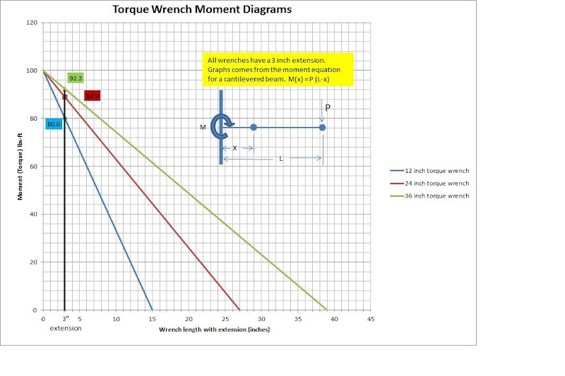
...The moment (or torque in our case) along the beam is given by the linear equation M(x) = P * (L-x) where M is the moment, P is the force applied at the handle, L is the overall length of the beam, and x is a distance from the cantilever fixed end (the bolt in our case)...

Very good, let's follow up on that.

We start by recognizing that the torque wrench plus the extension, represented here by the line between M and P, is what we call a rigid body. Yes, it pivots a tiny bit at the head (represented here as a point X inches to the right of the nut at M) in the process of measuring torque. But not much, so for our purposes we can assume that it is completely rigid. If we were evaluating its dynamic behavior it would be different, but we're not so it doesn't. When I'm flying I care about wing flutter, when I'm rock climbing I care about gate flutter, but I don't hardly ever care about wrench flutter.

Now, let's say we are using a torque wrench that is 36" from handle to drive lug. When we add the 3" extension to it, the system length L is 39". In feet, that is 39/12 = 3.25 feet.

Let's further say that we are looking for a torque at the nut of 100 ft-lbs. So let's solve our equation for P and find out how much force is required at the handle:

We start with:

M(x) = P * (L-x)

Solving for P and plugging in the numbers:

P = M(x)/(L - X)
= 100 /(3.25 - 0)
= 100 / 3.25
= 30.8 lbs

Let's run that back through the original equation to validate it:

M(x) = P * (L - x)
= 30.8 * (3.25 - 0)
= 30.8 * 3.25
= 100

So, we know that if we take a 39" bar and apply 30.8 lbs at the handle, we'll get our target torque at the nut.

Now, let's use the original equation again to see what the torque wrench reads when we are applying that 100 ft-lbs at the nut. Using our equation to find M(x), the moment 0.25 feet to the right of the nut where the head of the torque wrench is:

M(x) = P * (L - x )
= 30.8 * (3.25 - 0.25)
= 30.8 * 3
= 92.4

That tells us that with the 3" extension on the 36" torque wrench, the wrench will read or click at 92.4 ft-lbs when the torque at the nut is 100 ft-lbs.

That also tells us that the correction factor we would apply to the wrench reading or setting to get the correct 100 ft-lbs of torque when using the 3" extension is 92.4/100 = 0.924.

That is right in line with the equation in AC43.13 that is basically the rule of law among A&P and IAs and disregarded at their peril:

Y=T*L/(L+E)
=100*3/(3+0.25)
=92.3

Now, suppose that instead of the AC43.13 correction factor, we used the constant 0.8 correction factor that Allan dictates.

100 * 0.8 = 80

That would tell us that if we wanted 100 ft-lbs of torque and we believed Allan, we would either watch the wrench for 80 ft-lbs, or set the click for 80 ft-lbs.

Let's work this backwards a bit and use our original equation to see how much force that requires at the handle:

M(x)=P*(L-x)

We know that M(x) is the moment applied at the head of the torque wrench, which is 3" or 0.25 feet to the right of the nut. Solving for P and then plugging in the numbers, we get:

P = M(x)/(L - X)
= 80 /(3.25 - 0.25)
= 80 / 3
= 26.7 lbs

Now, let's use the original equation again and see what torque we get at the nut when we apply 26.7 lbs at the handle 3.25 feet away from the nut. Remember, the nut is 0 feet to the right of the nut (it is where it is, right?) so x=0:

M(x) = P * (L - x)
= 26.7 * (3.25 - 0)
= 26.7 * 3.25
= 86.8 ft-lbs

What that means is that if we apply the mythical "0.8 correction factor," when using a 36" torque wrench with a 3" extension we would get an actual torque at the nut of 86.8 ft-lbs. That is 13.2 ft-lbs or 13.2% less than our 100 ft-lb target, and in some circumstances may constitute a dangerously loose joint.

Thanks, Bob K.
 
Last edited:
Reiley, I think that this discussion would have died a timely death a long time ago, except for the fact that it revolves around a very important, flight safety issue.

Allan states that there is a constant multiplier for his tool, that being 0.8. Others believe that this is incorrect. The difference might be the under-torquing of flight critical components.

I think that virtually all posts have been respectful, and I think that Allan has been accommodating and professional in his responses.

I hope that between the videos he suggests he will provide, and the others that have already been presented, we can find an answer that all can accept.

Respectfully,
 
Reiley, I think that this discussion would have died a timely death a long time ago, except for the fact that it revolves around a very important, flight safety issue...

That's the only reason I'm pursuing the topic. I've seen what happens when propellers fall off.

Thanks, Bob K.
 
Counter torque

I was taught that proper "counter torque" was critical when using the wrench. Bob, does the math prove that it makes a big difference? If so, where do you place the other hand for the counter force...at the nut or at the connection to the extension?
 
I was taught that proper "counter torque" was critical when using the wrench. Bob, does the math prove that it makes a big difference? If so, where do you place the other hand for the counter force...at the nut or at the connection to the extension?

You raise an excellent point!

The counter force, which keeps the wrench from collapsing or capsizing, must be applied only at the nut. Applying force anywhere else along the torque wrench or extension will disrupt the torque reading.

Thanks, Bob K.
 
"Counter torque"...

Is really counter FORCE. (oops, Bob beat me to it!)
Go back to Bob Kuykendall's drawings in post #150, and you will see where he drew in the counter force in some of his examples. This force is necessary to maintain all the parts in static equilibrium. You know this from experience if you use a wrench with socket extension on it that raises the plane of the wrench up above the nut, that in order to keep the socket from tipping over to the side, you need to push against the top (back) of the wrench to keep it straight.

If you have a crow's foot type of wrench installed, or a very low profile socket, you don't really need to push, because the nut or bolt pushes back for you with no error, since its all flat at the plane of the nut or bolt. The added side force on the bolt doesn't change its response to getting torqued.

Strictly speaking, the only accurate place to apply this counter force is at the nut or bolt. Anywhere else, and the added force will change the applied torque slightly. Realistically, its not going to make much difference as long as you push pretty close to end above the nut or bolt head.

This question is one of many that are answered automatically when the technique of "free body diagrams" is used. No one has yet here drawn a completely correct free body diagram. I'm resisting the temptation to write a short introduction to static equilibrium analysis (statics).
 
Mike,

This takes the length of the arm of the torque creating device out of the equation completely, other than Allan's tool there is effectively no arm to figure

There is no torque without an arm. Calculate the force on the arm to react against the motor torque and you are right back to a simple cantilevered beam.

Bob,

The equation given in AC43.13 is the moment equation just in a form with two torques. It can be easily derived by substituting:

W=T(l)/(l+x)

Let T=PL
and L=l+x

so W=T(L-x)/((L-x)+x)
or
W=T(L-x)/L
or
W=PL(L-x)/L
or
W=P(L-x)

Once again I just want to say I think Allan's wrench is a great idea, and probably using .8 wouldn't cause any problems since most everyone's torque wrench is probably close to a foot long. But, I think it is important to understand the ramifications of using a crow's foot. I, for one, have used a crows foot to torque most of my fuel fittings. This is application where I think knowing what torque you're applying is critical.
 
Mike,

There is no torque without an arm. Calculate the force on the arm to react against the motor torque and you are right back to a simple cantilevered beam.

Bob,

Yes, but in this case the arm happens to have my right hand permanently attached to it.:D

The "arm" of the handle on a typical cordless is somewhere around 4" I would guess, and that would equate to 300 lb/ft going into my hand and wrist. (still using the original 100 lb/ft figure)

There is no way I can hold that much if it were a simple lever.
 
...probably using .8 wouldn't cause any problems since most everyone's torque wrench is probably close to a foot long...

Sorry, but I don't agree with that. Get a one-foot ruler out and have a look at it; does that look like the length of the sort of torque wrench you'd use on 7/16" nuts? Remember, we are talking about a wrench specifically designed for propeller nuts.

Thanks, Bob K.
 
Bob K.:

Your analyses seem indisputable. However, I torqued the nuts on my Whirlwind constant speed prop today, and used a 1 foot long click type torque wrench that read out in foot lbs along with Alans extension. No debate here, since we are all in agreement for that case. My point is that 1 foot long torque wrenches using ft lbs are common place and work fine for prop bolts like mine and on the Hartzells.

Regards

Erich

Edit: the wrench seems longer than 12 inches because that measurement only goes to the center of the handle; the far end of the handle extens a few inches past that.
 
Last edited:
Back
Top