What's new
Van's Air Force

Don't miss anything! Register now for full access to the definitive RV support community.

Review my systems diagrams please!

Craw

Active Member
Gooday Folks,
I have completed what I believe to be a good first draft of a G3X IFR setup for an RV-7A I'm building. This is my first pass so please be gentle.

I'm looking for a review of the drawings I've done and have provided links to a high-level pdf for the power distribution as well as a detailed set that includes everything. Just a few notes for anyone brave enough to review my layout:

1. I intend to fly with a backup handheld radio in case I ever need to run of the IBBS. That would allow me to land ASAP using the backup avionics and G5 along with the handheld and an iPad.

2. I will be installing a TailbeaconX ADSB-Out antenna so need a separate set of strobes to cover the full range as the tail light provided by FLY LEDs wont be installed.

Thanks all in advance for your input and please let me know if you find a ground or pin that is wrong or mislabelled.

---Note--- 02/11/22
I amended the drawings to incorporate some of the feedback provided in this thread and other omissions I found:
- Re-ordered centre stack to put the GTN GPS as high as possible without behind panel interference.
- Separate power pins for left and right landing lights to support the VP-X Pro Wig Wag function via pulsing to the different power pins (thanks Paul!).
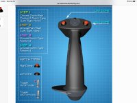
- Updated stick grip images to be consistent (note the stick grip shown on one image has an aux toggle switch the actual sticks have momentary push button).
- Added missing yellow line for input on stick grip wiring.
- Replaced erroneous circuit breaker icon with correct fuse icon.
- Updated ANL/Alternator & Contactor placement on Overview diagram.
- Re-ordered switches to provide better flow management given available panel space and avoid one straight line of switches across the bottom.


All the best!
 

Attachments

  • BACKBONE_ARCHITECTURE_PWR_DISTRIBUTIONV1.0.pdf
    587.4 KB · Views: 167
  • C-GXAW Detailed Systems Drawingsv1.1.pdf
    5.9 MB · Views: 127
Last edited:
Phil,

Some thoughts:
- As you already have the GNC255A NAV/Comm, why not use the GNC355 GPS navigators instead of the GTN-650? One NAV is more than enough and you will save ~$5K.
- While using a handheld is viable for backup, this means your minimum equipment list now has three comm radios. Alternative is to have reliable backup power for your Comm #2 as well as your audio panel and XPDR. If you stay with the hand held, don’t forget to add a way to connect it to both your headset and an external antenna (the standard rubber duck antenna is simply unacceptable for this application).
- Consider reordering the center stack. You want the GPS navigator as high as possible. Below that I’d put the NAV/Comm, then the autopilot, leaving the audio panel for the bottom as it tends to not be touched very often. If you have behind the panel space issues, then just do what you can to get the GPS navigator as high as possible.

Carl
 
Thanks for your feedback Carl, all valid points. I was planning on using the GTN635Xi which has the built in COM and not the NAV like the 650. I didn't realize the GNC355 had a built in COM. To be honest I'm unclear on the difference between the GNC355 and the GTN635Xi are at this point other than a marginally larger screen.

Does the GNC355 provide all the same capabilities as the GTN635Xi?

Thanks again
 
How high?

Phil,

Some thoughts:
-
- Consider reordering the center stack. You want the GPS navigator as high as possible. Below that I’d put the NAV/Comm, then the autopilot, leaving the audio panel for the bottom as it tends to not be touched very often. If you have behind the panel space issues, then just do what you can to get the GPS navigator as high as possible.

Carl

So on my panel, I did the opposite, the AP panel is on top, then the audio, then the nav.
The nav is so long it couldnt go any higher because it will hit the center rib on the RV7/9(A). And the only thing that would fit on top was the Autopilot Control head.

I like the audio up high because that is what my passengers will be playing with the most, so high so I can see what they are doing. But this is just me.
 
Thanks for your feedback Carl, all valid points. I was planning on using the GTN635Xi which has the built in COM and not the NAV like the 650. I didn't realize the GNC355 had a built in COM. To be honest I'm unclear on the difference between the GNC355 and the GTN635Xi are at this point other than a marginally larger screen.

Does the GNC355 provide all the same capabilities as the GTN635Xi?

Thanks again

The short answer is no. The 635XI advertises a "multifunctional" display. But shoot fire, with two full EFIS screens you need another multifunctional display like a hole in the head.

You do need a Comm #1 and a TSO GPS navigator for IFR work. The 355 does this and more. Save the $4K between the 635XI and the 355.

Carl
 
Up here in Canada we need to have two INDEPENDENT navigation sources to ben certified for IFR flight. Something like a GTN650 will not count as two as the GPS and NAV are in the same physical box. You need a separate nav device of some kind.

In my Bearhawk I am putting a GTN625 and an MGL N16 (with a G3X Touch system) to satisfy the IFR requirement...
 
The 635 multifunction screen is too small for displaying navigation information. However, it does give more entries of the flight plan than a smaller screen, so it is worth having for that. And it’s very clunky to edit an IFR flight plan on the G3X.

Autopilot goes at the top. If you’re IFR, it minimizes vertical head motion. Also, it lets you push the buttons without your hand obscuring your sight.

With flip/flop radios, it’s likely rare that you’ll be switching comm radios. I’d put the audio panel at the bottom of the stack, set and forget.

Cannot read the switches. However, having a long row of switches is bad form. Better to break it up into groups of three and four so you can find things more easily.

On my plane, I wish it used the second power inputs to the G3X touchscreens direct to the battery for uploading databases. To be honest, not sure how necessary this really is.

I have both autopilot servos on the same switch, don’t see any reason for separate switches.

You'll get more opinions in this forum than you'll know what to do with!!
 
G'day Phil
Opinions following!

1: The TailBeaconX is a position light only and is not a strobe. Mount it inside a wingtip instead where it can still do its ADS-B duties.
If you're short on power pins you could power it from the position light circuit, just as they had anticipated it would be in retrofit installations.
Use the Flyleds tail light you already have instead.

2: Doing point 1 above means the external strobes would then not be required.

3: The VP-X will automatically wigwag the landing lights for you above/below a set airspeed, so no extra panel switches required, however you will need to assign two separate left and right landing light output pins. See the VP-X manual for further info there.
Ignore/bypass the landing light green terminal block on the Flyleds controller board.

Nice first draft!


Impressive

This is inspiring. I'm at this stage of my build and have not been able to push through the there's-so-much-to-think-about-where-do-I-start. Impressive.
 
Thanks Ed,
I agree with the Audio panel reposition and it would bump up the GPS and GNC. I believe the passenger could control volume via the physical headset, thus negating the need for them to interface wit the panel. With regards to the switches I completely agree, unfortunately the AV-20E is taking up the real estate where I would like to put the Master/Alternator Field and P-MAG switches. That configuration would have provided for better flow management. Unfortunately the only Garmin Diversity ADS-B solution is significantly more expensive than the TailbeaconX and would require a second ADS-B antenna top side which I don't have the real estate for. One could however argue that it is a drop in the bucket when compared to the price of the entire system.

Thanks Paul and great catch! I have already assembled all the FLY LEDs works kit short of installing them on the physical wingtips. The kit was so much fun to build, the instructions were excellent.
 
Last edited:
Thanks Paul and great catch! I have already assembled all the FLY LEDs works kit short of installing them on the physical wingtips. The kit was so much fun to build, the instructions were excellent.
 
Last edited:
This is inspiring. I'm at this stage of my build and have not been able to push through the there's-so-much-to-think-about-where-do-I-start. Impressive.

Hey Eric,
This entire project is a like eating an elephant I to was over whelmed when I started looking into the electrical wiring and systems as it was mostly an enigma to me.

The way to get around it is by starting with someone else design as a baseline (I used my EAA chapter presidents design for his under construction Bearhawk). I literally copy pasted his power point slides (I can send you my deck if you like) and then started with one of the most basic elements, the lighting. This required some back and forth between the VPX-install Manual and the FLY LEDs instructions (I still got it wrong but thanks to Paul and this review the issue has been addressed). By the time I was done with that I picked away at all the other items which required flipping through several install manuals. The G3X Manual is 1000 pages but it is very easy to navigate and extremely well laid out. I would assume its the same for Dynon and some other manufacturers. I have enjoyed the process and it allowed me to visualize what each wire connects to as well as where and how. You get the added bonus of understanding how everything works together as system and it will have a deeper understanding of your airplane in the end.

Take your time do multiple reviews and when you think you have it right post it here for a review. Just keep at it... Power Point as well as MS Paint are easy tools to use but Visio is better if you have access to it. I also used the freeware on the following website for the panel layout its very easy to use and free: https://hangarflying.com/

Going through the Bob Knuckells book helped but I didn't do a deep dive as not all of it applied.

All the best
 
Last edited:
Gooday Folks,
I have completed what I believe to be a good first draft of a G3X IFR setup for an RV-7A I'm building. This is my first pass so please be gentle.

I'm looking for a review of the drawings I've done and have provided links to a high-level pdf for the power distribution as well as a detailed set that includes everything. Just a few notes for anyone brave enough to review my layout:

1. I intend to fly with a backup handheld radio in case I ever need to run of the IBBS. That would allow me to land ASAP using the backup avionics and G5 along with the handheld and an iPad.

2. I will be installing a TailbeaconX ADSB-Out antenna so need a separate set of strobes to cover the full range as the tail light provided by FLY LEDs wont be installed.

Thanks all in advance for your input and please let me know if you find a ground or pin that is wrong or mislabelled.


All the best!

Looks like a nice panel so far.

Not sure of Canadian ADS-B requirements but nonetheless confused of your choice of transponder. Since it's very much a Garmin panel with 2 G3X screens, the radios are not anything more than data entry devices, and really the G3X screens can handle most of the flight plan building.

To display ADSB on the G3X, I'd recommend you look at either of these:
https://www.aircraftspruce.com/pages/av/adsb/garmingtx45r.php

or

https://www.aircraftspruce.com/catalog/avpages/garmin_11-17227.php

If you go with the second choice, you satisfy both a second independent position source (for IFR as req'd in CA) and the transponder in/out functions.

But I'd recommend a review of the transponder choice regardless. It would also get rid of 1 antenna, since the garmin transponder can use just 1 ant for in/out.

Otherwise, looks like a nicely organized panel.
 
Not Worthy

Brilliant!! So many times I get on this site and am reminded that I am outclassed by you guys. I don't know if everyone who builds an RV does what you have done here but great work. But.... even though I'm not worthy, I will toss in a little more opinion!

1) I flew F16's for 20+ years and that was the airplane that pioneered HOTAS. As the airplane matured though, the throttle and stick got very busy. in your diagrams you show two different stick models. I don't know which you are planning to use but I would highly recommend you go with a hat switch for your trim vice four buttons. Unless you fly two or three times a week or are just better than I am (which is very possible) you will find streamlining the stick will pay dividends.

2) I will second the opinion that says A/P on the top of the stack. You will use it a bunch and it needs to be easy to see and easy to find. Build the panel in a way that is very usable in flight. It is very easy to manipulate switches and such at zero knots and one G but once you get busy, that can change very quickly. Also, I'd put the audio panel on the bottom of the stack, same reasoning.

3) Someone said earlier that it made more sense to group your switches than to have them in one big line. I tend to agree. I grouped mine by system for the most part. The exception is my Boost Pump/Landing Lights/Pitot Heat/Flaps.. I grouped them in their own section because I use them all the time. The remainder of your switches are generally used for setup on the ground and emergencies. These four, are busy switches that I use every time I take off and land so I put them together. My overarching goal with the panel is to build it to be as user friendly as possible when airborne. In fact, on mine I'm even taking into consideration my bi-focals...

One question, and it is only a question.. Why a Mini Key Switch and a Push To Start? Seems to me it just increases your potential points of failure with little gain. honestly just a question.

All in all, like I said before, brilliant!!
 
Thanks much for the feedback Grinch and I merely stand on the shoulders of giants. With regards to the stick grips excellent catch, I do plan on using the same stick for both but used the wrong image on a few pages. Unfortunately Ray Allen no longer sells the version with the HAT so I have to go with the separate trim buttons.

With regards to the mini key my thinking is its a simple way to prevent engaging the starter accidentally because of the push button and would be a minor theft deterrent (although anyone familiar with ignition wiring could hot wire it in minutes.

Cheers!
 
Last edited:
Tosten

Craw,
I just received my Tosten grips last week. Not installed yet but love the feel and ergonomics. Seem to be of high quality as well. I may be a little biased but I like the feel of the fighter stick as well.

Grinch
 

Attachments

  • 72364403-7F9C-4F27-8637-4B56922F2CAF.jpg
    72364403-7F9C-4F27-8637-4B56922F2CAF.jpg
    153 KB · Views: 85
Last edited:
Hey Grinch,
The Tolsten grips look awesome and Steve Thorn (Flight Chops) has them in his RV-14. That said I already bought my Ray Allen stick grips so maybe if I ever build another plane I will go for those instead.

All the best
 
Current limiter location

Looks like you have the current limiters at the alternator B terminals. They should be as close as possible to the contactor.
 
Back
Top