What's new
Van's Air Force

Don't miss anything! Register now for full access to the definitive RV support community.

What am I missing about this rudder stop?

IowaRV9Dreamer

Well Known Member
I've got the tail mounted to the fuselage and am trying to install the Vans rudder stops. I'm not exactly sure of the travel, but something seems to be wrong:
100_0887.jpg


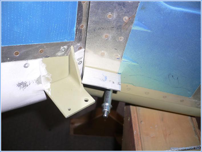
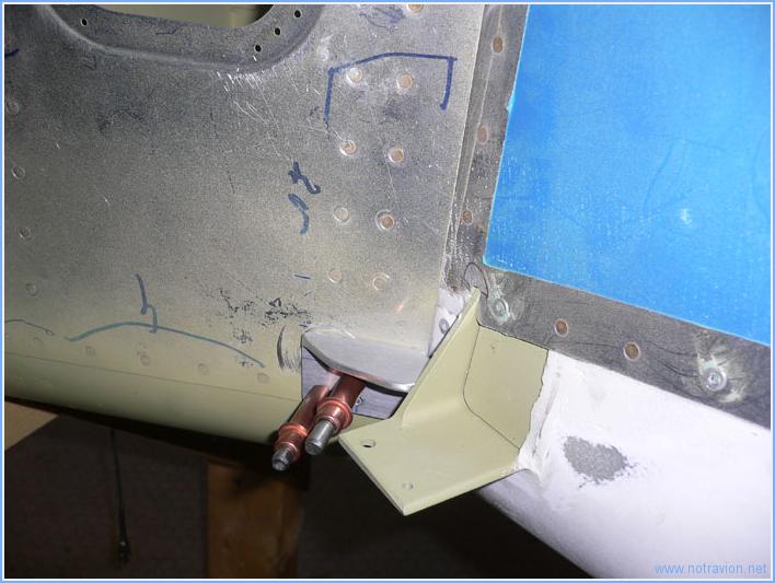
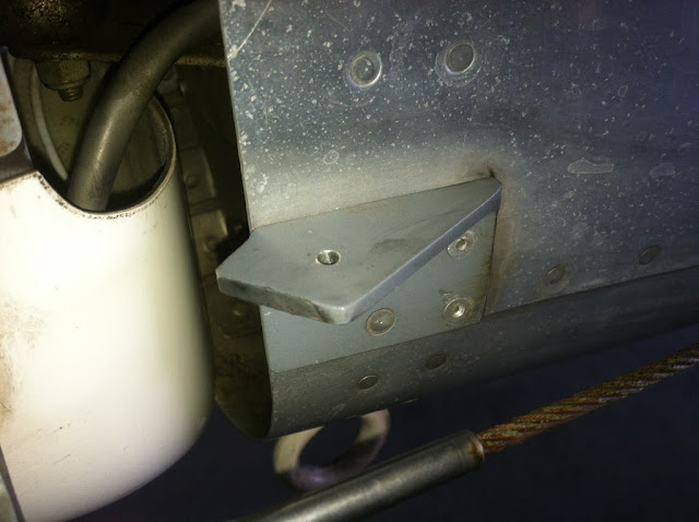
The rudder stop isn't able to hit the arm - it runs into the rudder's spar first. In the picture of the left rudder stop, I have the rudder in the approximate 35 degree position. You can see that the rudder spar (painted grey primer) it touching the stop. If I were to move the stop back to engage the control bar the problem just gets worse.

The rudder stops seem pretty close to the plans drawings. I think the rudder travel is right-ish. If anything it might be too low. I may need to extend the rudder rod end bearings a turn or two, because the rudder is just touching the VS at what I think is 35 degrees.

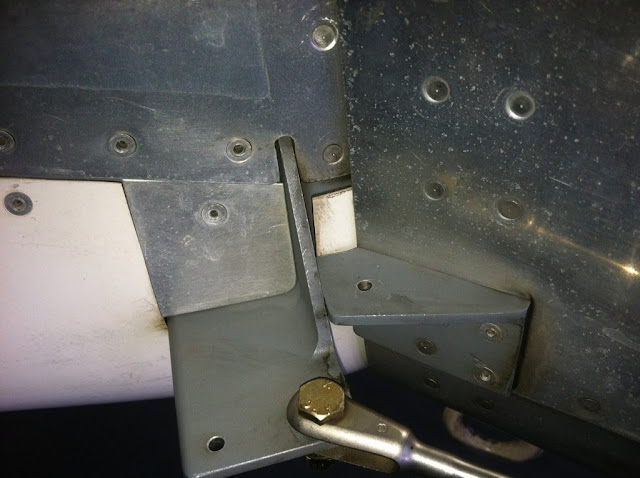
Someone please tell me what I"m doing wrong! I can't move the rudder stop down under the spar, because then it just barely lines up with the control bar.

At about 35 degrees, there is a bit under an inch of clearance between the rudder and elevator. Can any RV-9A people verify that?

Argh - I'm starting to want one of those delrin stops.
 
Too far aft

Your photo is showing the stop too far aft. If I remember correctly, the aft end of the stop pretty much lines up with the aft edge of the fuselage rather than extending out as shown in your photo. Also, on my 7, rather than cutting the aft bevels on the stops ahead of time, I clecoed the stops on and incrementally trimmed the aft bevel angles until I got to the proper rudder swing.
 
Last edited:
I ran into the same problem. My solution was to remake the stops and extend the horizontal portion back further by about a half an inch. I can take a picture on Saturday if you would like to see mine.
 
I had the same problem

I had to fabricate another pair of stops, because the orginal ones allowed the rudder hit the elevators.

I riveted my new ones on top of the orginals. That way, the new ones hit the correct place on the rubberbar.

The left and right rudder-deflection met the requirement in the manual with these new stops.

On my second -7, we ran into exactly the same problem and we've solved it the same way.
The same mod has another Norwegian -7 builder done.

 
Last edited:
The plans are wrong!

I found this while building my early 70172 RV7A. If you build them per the plans they will be wrong. I used mine to measure from to make the second ones correctly. I looked at the one on the company plane while at SnF and found theirs looked just like my corrected ones. I don't understand why they won't fix the plans to show the correct way to make them. There has been a lot of rudders damaged from these stops not extending far enough. Ill try to get a picture today.
 
This is my version, picture is not that good.
The horizontal part of the stop is going further aft that the plans show, the aft angle is also different to allow for the correct rudder throw.

This is the fitting picture
large_RearFuse_040_1b0b1c.jpg


And the finished stop :
large_RearFuse_041_1d5725.jpg
 
Last edited:
You are not missing anything - the plan is perfect for the original RV6 rudder. I built the tall rudder and had the same issue. just make it go beyond the back face of fuse at the expected angle of the rudder at max. Leave the pointed end, and use a file to adjust, then make it pretty.

IMG_0791.JPG


IMG_0787.JPG


My illusion of building exactly to the plan was shattered by this, but I learned that they are not perfect and you will find more issues, so keep thinking. 99% + they are correct, but . . . This why I donate to VAF now. You are fortunate to build your whole plane, by the end (or soon) "you won't need no stinkin' plans!"

Happy building and learning.
 
Easiest way to do the rudder stop is attach it like you've got it (with clecoes, of course), then take a file and just keep filing until it hits the stops, then just keep filing until you get the proper limit angle as indicated in the instructions.

Same deal with the elevator stop.
 
This most certainly won't be the last time you build it exactly to the plans and then look at it for a while saying "That just won't work!"

There are some (several) points in the plans that need some updating, but if you'll do a search on the forums here when you run into one of those spots, odds are good you'll find the solutions discussed in here.
 
As has already been stated, the plans are wrong. Make a part that will work per the intent.

In regards to the internal stop, make your own choice and remember that on the internet you can always find the answer you want to hear.

Pics of my rudder stops
 
Last edited:
Thanks guys - I did a quick search but somehow missed the point that the plans are WRONG. My stops as-is may not be ablle to be used. I'm going to look in the scrap bin and see if I have anything that will work.

Are the internal stops even still available? I like the idea of pressing against the big bar rather than the rudder spar.

Anybody with a flying -9 able to measure the horizontal distance between elevator and rudder? I think it will be a bit under an inch, which seems close.
 
Last edited:
Easiest way to do the rudder stop is attach it like you've got it (with clecoes, of course), then take a file and just keep filing until it hits the stops, then just keep filing until you get the proper limit angle as indicated in the instructions.

Same deal with the elevator stop.

I would do it like Bob suggests. You really want to make sure the stop is flush against the horn. I think I set mine so that there was about 1.5-2" between the rudder and trailing edge of the elevators when hard over.
 
I think I set mine so that there was about 1.5-2" between the rudder and trailing edge of the elevators when hard over.
Vans gives a measurment like 46 1/8" from rudder trailing edge to elevator trailing edge for 35 degree throw. If I position it there I get less than an inch of clearance. I think we are allowed to have rudder throw as low as 30 degrees, so maybe I'll see what that works out to in terrms of gap between elevator and rudder.
 
I found this while building my early 70172 RV7A. If you build them per the plans they will be wrong. I used mine to measure from to make the second ones correctly. I looked at the one on the company plane while at SnF and found theirs looked just like my corrected ones. I don't understand why they won't fix the plans to show the correct way to make them. There has been a lot of rudders damaged from these stops not extending far enough. Ill try to get a picture today.

Got those pictures, This is the way they should be made and the way they look on the factory plane (not per the plans):

IMG_00956.jpg" height="478" width="640"


IMG_00957.jpg" height="478" width="640"
 
Thanks Bobby and all who posted. Your pictures made the difference. The rudder stops came out super solid.

I ended up adding some metal to the underside of the stops as I didn't have enough material to make new stops and I really wanted to get this done tonite. It is the last "thing" before disassembling the airframe and letting the wife's car back in the garage :rolleyes:

I ended up with 35 degrees in each direction, measured with an angle finder and some homemade paper triangles. I have 1 3/8" clearance between the elevator and rudders, and 47 3/8" from rudder trailing edge to elevator trailing edge. Doesn't match the numbers in the manual that well, but they are probably just as wrong as the rudder stop on DWG 27A.

OK - now for a rant. Please ignore as needed:
If "everyone" knows the rudder stop drawing is NG on DWG 27A, and if it is different on the FACTORY PLANE, why doesn't Van's either:
a) revise the drawing with a correction
b) revise the drawing with a note "This is incorrect"
c) Issue a revision note / construction bulletin online

I know a bit about engineering... and what ECOs cost... but there is also right and wrong. I didn't need a new dimensioned drawing, but an isometric of the new part would have helped. It can't be that hard for them. This is one of the few areas that I've found where the plans are flat out wrong (not just with missing info). On the opposite side, I bet they sell a lot of rudder stop material!

Whew, rant over. Thanks for listening.
 
I had to fabricate another pair of stops, because the orginal ones allowed the rudder hit the elevators.

I riveted my new ones on top of the orginals. That way, the new ones hit the correct place on the rubberbar.

The left and right rudder-deflection met the requirement in the manual with these new stops.

On my second -7, we ran into exactly the same problem and we've solved it the same way.
The same mod has another Norwegian -7 builder done.


Why have those cable connections to the rudder been done that way? That will introduce a twisting moment in the corner of the rudder bar that it may not be designed to take. If those washers are ever orientated with the sheared edge against the bar that`s not good a good situation. When is a failure most likely to occur if it does? The right side on the take off roll? Ouch...
I`m building a 7 with no bushing in the rudder bar and the drawing clearly shows a direct cable connection. Just my opinion, but that doesn`t look right to me at all. Is the 9 drawing the same as the 7?
 
Last edited:
I found the plans to be correct in this case. The rudder deflection is adjusted with the position of the rod end bearings in the rudder. I found that moving the rudder closer to the VS will decrease the rudder deflection and give the desired amount of clearance between the rudder and elevators. The stock stops worked for me.
 
You guys know those bolts on the bar aren't torqued down, right? Those bolts move freely. Same as the bolts on the connection at the pedals.

Yes Sure, but that rudder cable isn`t pulling in a direct line from the rudder bar, its cocking the swivelling bolt off in the hole and trying to twist the end of the rudder bar.
At the pedals the bolts are not torqued but the cable connection pulls in a straight line from the connection point on the pedal assembly.

I`m just pointing out that whoever owns that aircraft may want to pay attention that the bar doesn`t crack.
 
Back
Top