What's new
Van's Air Force

Don't miss anything! Register now for full access to the definitive RV support community.

Sub-Panel CAD

GrinchF16

Well Known Member
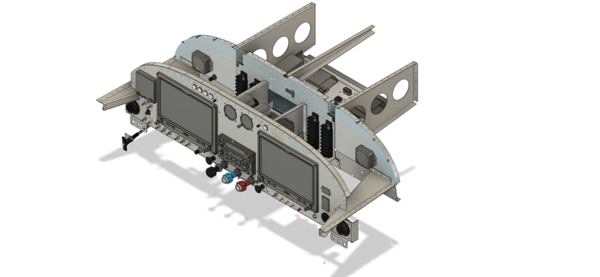
Does anyone have a CAD drawing for the sub-panel on a tip up RV7A? In the drawings I believe it is referred to as the sub panel, it is located between the instrument panel and the firewall. Mine looks like the builder took a sawzall and a sledge hammer to it to make pieces fit.. I would like to clean it up and mount some remote avionics to it.

Thanks
 
Sub-panel avionics location will vary depending on tip-up v. slider. My AFS Quick panel came with specific drawings for mounting locations for my slider. With both 10" displays removed there is sufficient room for access to remote mounted avionics and back-up battery.
 
Van's downloads page contains several useful CAD drawings. Their 3D assemblies are in "IGS" format, and depict the panel, subpanel, and surrounding structural metal. I used this 3D model throughout my panel/sp layout to ensure everything fit (including depth of panel instruments), and to precisely cut and re-position my F-745 ribs to accommodate two large screens. The 3D file you might be looking for is RV-7,RV-9 3D Panel Tip-Up Canopy

 
Thanks guys. What I am looking for is the actual drawing to cut out a replacement sub panel. I think I have come up with an alternative solution though…
 
Back
Top