What's new
Van's Air Force

Don't miss anything! Register now for full access to the definitive RV support community.

Fuselage cable routing question

Bill Boyd

Well Known Member
Contemplating wire runs from the battery and tail forward to the cockpit/panel area, while my build is at the full-length canoe stage. I see lightening/pass-through holes aplenty in the bulkheads on the right side, but they vanish at the spar web carry-through. What's the secret for routing cables forward further than the spar center section? Can they go over the spar but under the front seats? I lack a completed 10 to look at, so any description of what I should be doing to install conduit and route cables from tail to nose while I have decent access to the aft tail cone area would be appreciated.
 
Typically moving aft to forward a lot of folks install conduit under the baggage area and aim towards the sides by the rear seats to route wires up both sides over the spar.
 
Last edited:
Typically moving aft to forward a lot of folks install conduit under the baggage area and aim towards the sides by the rear seats to route wires up both sides over the spar.

Yep, what he said.

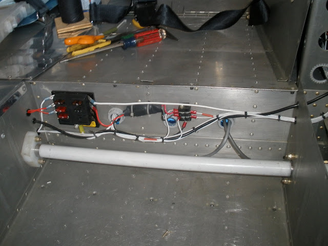
Conduit under baggage.

P5110057.jpg


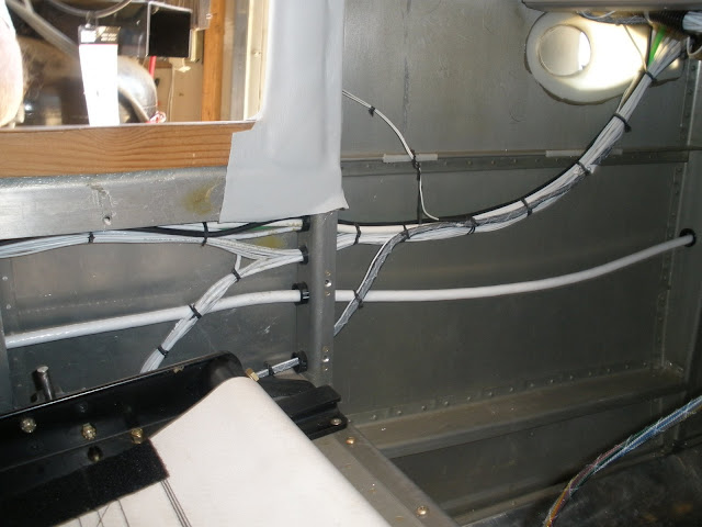
Side over spar/under door.

P5130009.jpg


You can get a lot of wiring through this area if you take your time and plan the routing.
 
a baggage compartment option

I am running two ~3/4 conduits under each side of the baggage area, holes already there, just made a bit larger. They exit nicely in the area that is always fully accessible. Once at the seats they go up and through the 2 5/8" bushings each side that gets us to the panel. I am also making the baggage compartment side cover (right side) removable so I can gain access to that area for a wire run coming through F-1006C. I just prefer to see and inspect wires if at all possible.

With current led lights, dynon txpder/AP servo, battery, and ELT in the back, I have very few wires, and most 20 to 22 gage, running to the back of the plane from the panel, barely enough to fill one 3/4" let alone two. Since COM antennas etc and of course all the wing wiring never need go past the passenger feet area and avionics are getting smarter and draw less current, the need for a lot of "wire capacity" is low on my radar.
 
They add up...

Been doing some thinking on this lately and the wires do start to add up.

For example:

LED tail light/strobe - 5 wires (PWR pos, PWR strobe, Sync, GND, Shield)
Elevator Trim - 5 wires
Pitch Servo - 6 wires
Magnetometer for G3X - 7 wires
Main Battery - 1 BIG wire (maybe two)
Master wiring - 1 wire
ELT activation - 1 telephone style cable

and that doesn't include any other things that might be located back there. I am of the opinion that I would rather have too many conduits beneath that area than not enough...
 
Pleading ignorance

Yep, what he said.

Conduit under baggage.

P5110057.jpg


Side over spar/under door.

P5130009.jpg


You can get a lot of wiring through this area if you take your time and plan the routing.

The pictures with the electrical insulating bushings make me think you are actually using PVC conduit and not the flexible (black) conduit Van's sells or is available from automotive supply houses?

If it's the flexible conduit, how are you attaching the bushings to the end?

Starting fuselage build next month in Oregon - so trying to understand the best practices of the experts that have figured it out.

Thanks much!
 
The pictures with the electrical insulating bushings make me think you are actually using PVC conduit and not the flexible (black) conduit Van's sells or is available from automotive supply houses?

Yes, correct.

If it's the flexible conduit, how are you attaching the bushings to the end?

They just glue on with PVC glue.

Starting fuselage build next month in Oregon - so trying to understand the best practices of the experts that have figured it out.

Not an expert by any stretch of the imagination----just showing how I did it.

Thanks much!

See answers in red.
 
ran a quick experiment...

Ran the test to back up my "estimate" on the 3/4" bushing capacity. Certainly understand the idea of more is better, running out just creates a bit of a mess....

So here is what fit in one 3/4" std vans bushing...

Dynon AP std connection (6 wires) with gnd at servo
Dynon txpder power & communication wires (3) with local gnd
#2 gage for battery pos and 2 x 18 gauge for power up and back to master
ELT "telephone wire"
strobe, position, and sync (2 x 20 with 22 ga sync), ground local at back
2020 GPS wires, std Dynon install with 4 wires to panel
single 5-wire bundle to elevator trim

What remains in my install is the 1/4" static line up front. This will leave enough room for about 20 x 20 gauge wires aft of the baggage compartment or other big wires like another #2 for gnd if one choses. Note I did not even include the access I am planning along the right side baggage panel (removable). This will be my, oh forgot about that.......:) place to escape and still look very tight and professional.
Cheers, Mike
 
step access panel in baggage floor

Bill,
One last comment, I followed some advice on the forum about installing inspection panels (std vans used on stall warning indicator access) in the baggage floor just over the step attachment bolt, saves needing to drill through the bottom skin, allows for step adjustment and/or replacement, and gives great access to this area that is prime for running wires/conduit . Provides easy inspection in that covered area which I really like to have as well for many years to come.
Cheers, Mike
 
Yep, what he said.

Conduit under baggage.

P5110057.jpg


Side over spar/under door.

P5130009.jpg


You can get a lot of wiring through this area if you take your time and plan the routing.

So, it's okay to drill holes in those side formers that attach to the spar web below the door opening (Sorry - no plans with me at work today for proper part call-out). Mine are presently undrilled, and I was not sure it was okay to violate them :(

Makes perfect sense, though. I presume one stays small and in the center of the web with whatever holes are needed here.
 
Thanks, Mike.

Bill,
One last comment, I followed some advice on the forum about installing inspection panels (std vans used on stall warning indicator access) in the baggage floor just over the step attachment bolt, saves needing to drill through the bottom skin, allows for step adjustment and/or replacement, and gives great access to this area that is prime for running wires/conduit . Provides easy inspection in that covered area which I really like to have as well for many years to come.
Cheers, Mike

Pretty sure that my previous builder (shall I call him my ghost-partner) installed said inspection plates. I will look again to be sure. Haven't gotten that far yet except to catalog where the parts are now stored in my shop. I plan to use the anti-crush bushings in the step tubes, but access would still be nice.
 
So, it's okay to drill holes in those side formers that attach to the spar web below the door opening

As I recall, they were already there, except one. I checked with the factory before drilling that one, and got the OK on it.

Pretty sure the plans show at least the pitot/static lines, and the main battery cable going through these holes.

Been 6+ years, so my memory may be a bit fuzzy......
 
Looks like only one hole to start with

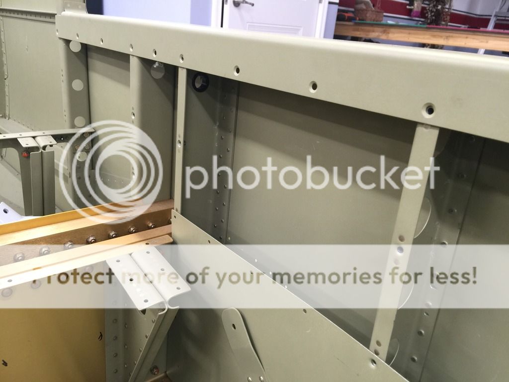
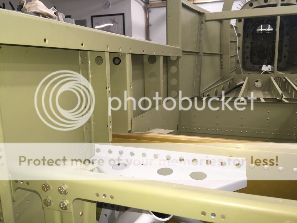
I didn't even notice the hole was there, complete with bushing, until I took the pics last night to post here, but there is one predrilled factory hole at the top of the F-1004 C and D's. It's visible in the pics. Curiously, the plans I have (Rev. 0) show two holes per piece on pp. 28-1, 28-9 Fig 1, for example.

Good to know the factory approves additional holes here.


Mike, your pics show the F-1042's primarily, but I can see there must be some extra penetrations of the F-1004-C's and D's as well for the cables I see. Am I right?
 
Last edited:
Bill,

I think you'll find another set of fore and aft holes in those bulkheads, up higher and hidden by the structure under the door opening.
 
...and

I'd be willing to bet you're right, Kyle. Will eat crow here tonight after I poke around up there with a fingertip to verify.

Looks like Mike's B+ fat wire goes through lower down, through his additional hole. It's all coming into focus now. I'm one with the Force...
 
Yep

Two factory holes in each piece. Upper ones hidden under the "gunwhale" just as predicted. And here I thought I had done a pretty thorough inspection of the previous workmanship that had brought this slow build kit to the QB-stage.
 
I don't know what you guys are putting back there!

I have ELT, strobe pack, twin ADAHRS, AP servo, OAT probe, VHF antenna, electric trim and tail lights and I managed to get everything through the two conduits on each side recommended in the plans.

As far as I am concerned, any other holes compromise the structure.
 
Back
Top