

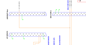
I am looking at two wiring diagrams. One is data connections from Advance Flights Panel. It shows connections from GPS and EFIS data.
The next diagram is from Onspeed AOA, it shows GPS and both EFIS RX and EFIS TX connected together.
Obviously, this works. I would like a better understanding of how these data sources can be connected together a still function.
Thanks
Max
The next diagram is from Onspeed AOA, it shows GPS and both EFIS RX and EFIS TX connected together.
Obviously, this works. I would like a better understanding of how these data sources can be connected together a still function.
Thanks
Max
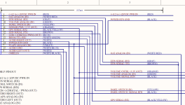
") We tie some serial lines together so we can test the TTL to RS232 converter chip in a loop. We built this test harness to test the hardware before we send them out to our beta testers.
We tie some serial lines together so we can test the TTL to RS232 converter chip in a loop. We built this test harness to test the hardware before we send them out to our beta testers.
