KatanaPilot
Well Known Member
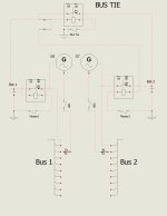
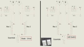
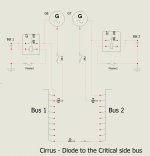
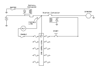
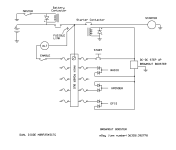
You start with two full battery / alternator /regulator / contactor systems splitting the avionics / devices so you can live on either and then for the SDS, you wire it up just as Ross draws it, i.e. take power from the hot side of
each contactor but add a diode in each line to only allow the flow from the respective bus to the engine bus. .
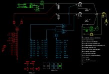
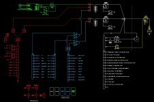
Assuming you have the dual ECU system - I’m not sure why you can’t wire for separate power sources. You have one ECU, fuel pump and coil pack on a respective (hot battery) bus. Injector power is determined by the PRI/BAK switch on a 4 cylinder. On the 6 cylinder power is separated 1,2,3 to one bus and 4,5,6 on the other or all on one bus - as determined by the PRI/NOR/BAK switch.
That’s how we did our RV-10. We have a cross tie that’s used only to tie both ETX-900 batteries together for engine start. No diodes required. Some intervention required if a bus is lost or an ECU fails.