What's new
Van's Air Force

Don't miss anything! Register now for full access to the definitive RV support community.

RV7 loose gear leg

crabandy

Well Known Member
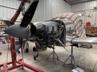
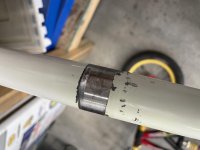
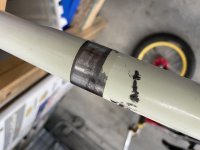
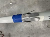
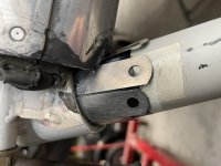
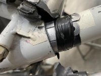
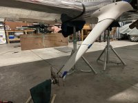
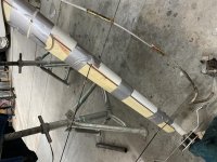
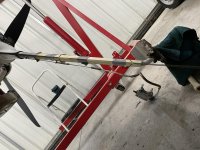
Doing the condition inspection on my RV7 (590hours) I found the left gear leg had some slop in it. It seems to be loose in the lower socket of the leg, the top bolt is tight and the leg doesn't wiggle.
I believe it is the same gear leg that I sometimes get a little shimmy in on taxi. Some grass field ops but most are very smooth.

https://andycrabtree.smugmug.com/N117TR-Condition-Inspection-11-2

I sent the video to Van's and waiting to hear back.
 
Last edited:
Sorry, different computers and software. Try it again

Yup, works now
icon14.gif


Thats some wiggle. I'm guessing if you removed the gear leg you'll find the lower socket elongated.
 
Vans and Langair have both advised the loose gear leg isn’t cause for major concern, more of a fly and keep an eye on it. I think it’s worth a try to fix the wobble now instead of flying with it loose.

A friend sent me Cessna’s Service Letter SE75-9 reference C180/185/188 tailwheel springs being bonded to the tailwheel bracket. It is removable with heat as described in the Service Letter.
The adhesive is $11.

https://skygeek.com/henkel-hysol-ea...MIi6Hirf6q9AIVvW1vBB3MLQgtEAQYASABEgK_wPD_BwE

Thinking this is probably my best option followed by replacing the upper bolt with a taper pin.

I’m not sure replacing the upper bolt with a taper pin will do anything. You said in your original post that the upper bolt is tight and there is no movement. Filling a minor void in the lower gear leg opening with some composite limits movement that may be a temporary solution that you could repeat by redoing it yearly, would be a simple option. Since Vans says it’s not an issue right now, I wouldn’t worry about it until it is. Filling the void now would delay that decision, which could be years down the road.
 
I pulled the gear leg, really wasn’t that big a deal. The gearleg and socket seemed to be wearing/elongating at about a 45* angle to the longitundinal axis of the airplane. Front lower portion and upper rear on a 45 to the longitudinal axis.
 

Attachments

  • 32FD390A-4D75-4EDB-859A-3B8C2A8C4AEF.jpg
    32FD390A-4D75-4EDB-859A-3B8C2A8C4AEF.jpg
    496.6 KB · Views: 466
  • B05056D0-F033-473E-95FB-EDCF2C1AAB93.jpg
    B05056D0-F033-473E-95FB-EDCF2C1AAB93.jpg
    210.9 KB · Views: 415
  • B5D85373-418F-4BCE-ACA6-354D5F62F37E.jpg
    B5D85373-418F-4BCE-ACA6-354D5F62F37E.jpg
    213.7 KB · Views: 391
Similar to Cessna’s service letter and other friends advice I decided to shim and use an epoxy adhesive. I would rather attempt this method and fly it and see what happens as to leave it loose and fly it and see what happens.

I did several rounds seeing what I could shim where, I was gonna use shim stock but nothing available locally besides feeler gauges which as far as I could find are basically the same. Dry test fit with the shims in place worked well, not so well with the adhesive epoxy as they just slid out of place. No biggie to reinsert the shims and now waiting for a couple days dry time.
 

Attachments

  • 21F1297D-3EFB-4111-9DF9-F8F82AF2B8F1.jpg
    21F1297D-3EFB-4111-9DF9-F8F82AF2B8F1.jpg
    190.6 KB · Views: 376
  • BE0619EC-B0EE-49CC-A3D9-094D8471A598.jpg
    BE0619EC-B0EE-49CC-A3D9-094D8471A598.jpg
    305.8 KB · Views: 393
  • C42CCF94-9F32-47B5-968D-27E01A63EAED.jpg
    C42CCF94-9F32-47B5-968D-27E01A63EAED.jpg
    299.2 KB · Views: 386
Grease

Andy

Was there any grease on these legs? As if they’re dry and there is movement then the leg and socket will grind. Does vans recommend putting grease on the leg?

Regards

Peter
 
Andy

Was there any grease on these legs? As if they’re dry and there is movement then the leg and socket will grind. Does vans recommend putting grease on the leg?

Regards

Peter

I wondered the same. this appears to be a sliding surface. would grease be beneficial to prevent wear?

I would never put grease between two bolted flanges because a properly designed bolted flange should carry the load in friction between the mating flange surfaces. if the bolted joint cannot carry the load by friction, the flange faces will fret and wear and the bolted joint will lose clamp and required constant attention. however, this is different, it's a rod within a tube and the bolted connection is at a distance away. I may have just convinced myself to add some grease to the lower portion of my gear legs.

note: a good conservative friction value to use for designing mating flanges = 0.1, example: where 1000 lbs of bolt clamp results in 1000(0.1) = 100 lbs of flange shear friction force capability per bolt. increase the number of bolts, bolt clamp (torque value or bolt size) to increase the flange friction load carrying capability. design criteria: under maximum load the flanges directly under the bolt should never become separated. reference bolted flange design course 101. :)

aluminum is a soft material and getting the correct torque is important. too much torque will damage the aluminum, not enough torque and you risk a loose joint. use a good torque wrench.
 
Last edited:
Andy

. Does vans recommend putting grease on the leg?

Regards

Peter

Yes, at least in my build manual. I assumed it was for corrosion reasons, but see how the grease can help to minimize wear in cases where the fit was too loose. Not sure what the tolerances are on the leg socket interface.

Larry
 
I would never put grease between two bolted flanges because a properly designed bolted flange should carry the load in friction between the mating flange surfaces.

It is not a flange interface. It is a socket. Pretty much all of the load is carried by the socket structure. The bolt just keeps the rod from falling out of the socket. This is no different from the bearing interface on your axle. The wheel transfers all of the load to the axle via the socket structure. The nut is just there to keep it from sliding off and carries no load.

Even on a flange interface, I don't believe friction is a strength component. It's all about the compressive strength of the stretched bolts. I am sure this varies a lot on what type of forces are being imparted upon the part. Many flange interface joints use a sealant, which also reduces friction.
 
Last edited:
My ancient RV6 plans say to use heavy grease on those two (per leg) cylindrical interfaces. I did just that on my 6A, and after a couple years I was getting creaking on the right leg over rough surfaces at a slow enough taxi speed to hear it. I pulled the legs and saw there was fretting in one area. I cleaned up the fretting and re-assembled with a lot more grease, and have had no further problems in 18 years.
 
The leg and socket were greased per the plans.

Langair mentioned loose bolts at the top, I’ve had to slightly re-torque on inspections but nothing major.

I did have a slight wheel shimmy, as I got more time in the airplane I found out how to avoid it. I always thought it was the copilots wheel but it’s possible it was the pilots side. I am currently adding the wood stiffeners.
 
I wanted add a link to another post I had checked out to solve my problem

Good morning

Not surprised to see another post on a loose gear leg. I guess as these girls are getting older they are starting to wear. I wanted add a link to another post I had checked out to solve my problem. My entries start around #15 but the last ones are more relevant and what I did to solve (and yes it’s still working without any shimmy((cross my fingers)) the shimmy.

I didn’t add any shims nor did I use an epoxy. I wish I’d seem this earlier as I think your on the right track. I research locktight and used that. Although you have a lot more movement than I did.

So for what it’s worth the link is below.

https://vansairforce.net/community/showthread.php?t=131399
 
bolt to keep gear from falling out

It is not true that the bolt is just to keep the gear from falling out. The geometry of the axle in relation to the upper portion puts a significant twisting load on the upper gear leg bolt.
Some Wittman Tailwind builders have created a clamp at the lower edge of the socket. Piece of heavy wall 4130 tube welded to the forward edge of socket and slotted after welding. Difficult to do with the mount installed.
I have a 1/4" x 1 1/2" 2024 bar attached to the trailing edge of may gear as discussed previously. Eliminated the worst of the shake. Balancing the wheel pant and balancing the wheel did not help.

Welding a tube clamp and slotting it was another idea that I was kicking around.

Added the wood stiffeners today, I should got a laser level years ago. I did several string line iterations with the fairings and stiffeners, my fairings were really close but have bowed due to gear shape sitting on the ground. Also wanted to make sure the stiffeners and fairings would also fit my intersection fairings.
 

Attachments

  • 7B735BEC-A700-4489-BD0E-711045E3AB46.jpg
    7B735BEC-A700-4489-BD0E-711045E3AB46.jpg
    418.8 KB · Views: 287
  • 8F4278D9-1889-4FDE-B3A4-CDDEC7DAE3BB.jpg
    8F4278D9-1889-4FDE-B3A4-CDDEC7DAE3BB.jpg
    414.7 KB · Views: 260
  • D17F315B-E9AA-429D-87EC-8BAAAC8047BB.jpg
    D17F315B-E9AA-429D-87EC-8BAAAC8047BB.jpg
    412 KB · Views: 246
Welding a tube clamp and slotting it was another idea that I was kicking around.

My -6 mount had cracks so I made some rings to go around the OD of the sockets shaped such to fit around the tubes and welds. When I TIG welded everything the socket ID shrank which made the fit with the legs slightly tight.
 
My Fix

Neither the upper collar with the bolt hole thru it or the lower collar offer a “size on” fit with the gear leg. Even if the sockets went through an ID grind operation and the gear leg was center less ground, you’d still need clearance.
Clearance at the top would require the bolt be tightened until it distorted the upper tube, and you’d still have to deal with clearance between the bolt and the cross hole in the gear leg.
Following some earlier posts, I pulled the gear leg and used a piloted reamer to size the cross hole(s) in the tube to give me a straight, precise bore for the bolt. Same reamer was used in the gear leg - this can’t be done the the leg in place. I used a ground to size bolt which had to be gently tapped into place when the leg was fitted back into the socket.
This approach eliminated any play at the top end, even though there appeared to be a couple thousandths of clearance between the upper leg OD and socket. The cross bolt did not have to be over torqued as loading was in shear, not tension/compression.
Play or wobble in gear leg went to zero, and nothing was done to lower contact collar or leg OD.
Just my $.02, and an idea posted over 10 years ago. Worked great for me.
Terry, CFI
RV9A N323TP

I was thinking about using a taper pin up top instead of the bolt, similar to the tailwheel taper pins I installed. I found nothing loose at the top bolt no matter what I shook. Without the gear leg installed the bolt in the mount does have a slight jiggle, the bolt in the gear leg is tight.

I used the same epoxy adhesive at the top joint as the bottom. I didn’t do the taper pin for now, we’ll see how this fix goes. If I find things starting to wiggle again I’m most likely going to add a Taper Pin.

I’m hoping gearleg stiffeners eliminate all shimmy and any loosening the gearleg, we’ll see. I figured worst case scenario I can re-shim and glue, hopefully it makes another 1500hours and I can decide it’s good enough or fix it when I pull the engine for overhaul.
 
Thoughts on taper pin

I first tried to ream with the gear leg in place and the bolt partially in to prevent movement. When the pilot on my reamer pushed the bolt far enough out, the leg clocked and locked the reamer in place. Scared the begeezus out of me as I contemplated removing a broken reamer from a partially finished hole.
Once I was able to remove it, I realized doing the parts separately was for me the only way to go.
With a taper reamer/pin, you’ll likely need to do the parts while they’re assembled. Very difficult to get a contiguous surface- that’s why I went with a straight reamer. Again, just my $.02.
Keep us posted with your efforts.
Terry

Thanks Terry, it all adds to the thoughts and ideas.
Was there weight on the gearleg as you were reaming or jacked up?

When I did my tail wheel I squared up a 2x6 with perpendicular supports on a 4’x4’ piece of 3/4 plywood. The tailwheel fork nestled over the 2x6 with shims to make the full width. I did leave 1 bolt in as I reamed the first tailwheel fork hole.
The single tailwheel spring to weldment hole I was able to ream the single hole with the tailwheel fixture holding it stead and the airplane holding the other half. I also reamed it by hand, I’m sure it might be different with power tools.
 
Last edited:
Thoughts on taper pin

I first tried to ream with the gear leg in place and the bolt partially in to prevent movement. When the pilot on my reamer pushed the bolt far enough out, the leg clocked and locked the reamer in place. Scared the begeezus out of me as I contemplated removing a broken reamer from a partially finished hole.
Once I was able to remove it, I realized doing the parts separately was for me the only way to go.
With a taper reamer/pin, you’ll likely need to do the parts while they’re assembled. Very difficult to get a contiguous surface- that’s why I went with a straight reamer. Again, just my $.02.
Keep us posted with your efforts.
Terry
 
Similar to Cessna’s service letter and other friends advice I decided to shim and use an epoxy adhesive. I would rather attempt this method and fly it and see what happens as to leave it loose and fly it and see what happens.

I did several rounds seeing what I could shim where, I was gonna use shim stock but nothing available locally besides feeler gauges which as far as I could find are basically the same. Dry test fit with the shims in place worked well, not so well with the adhesive epoxy as they just slid out of place. No biggie to reinsert the shims and now waiting for a couple days dry time.


Slip fit loc tite (green), but you will never get it out later... I used it to solve the same problem on an Arion Lightning main gear leg which is the Vans gear leg.
 
Work Hardening

I didn't see it mentioned but there are going to be cracks here.

Not saying when, not saying soon. Everything will eventually come apart by work hardening and fatigue failure if it is in service long enough. Since there is some obvious work being done to that metal both above and below, one should expect cracks sooner.

1000 more hours, 4000? 8000? I don't know but I'd bet there is somebody that could put a ballpark on it with enough data on RV trends.

I would certainly be hot on checking every time I had that area exposed, smooth out any stress risers and guard against corrosion.

If somebody covered this earlier and I missed it then I apologize.
 
Last edited:
Back
Top