What's new
Van's Air Force

Don't miss anything! Register now for full access to the definitive RV support community.

Another "Routing Wire" thread

wirejock

Well Known Member
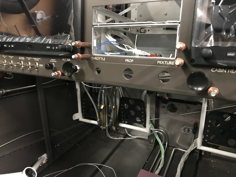
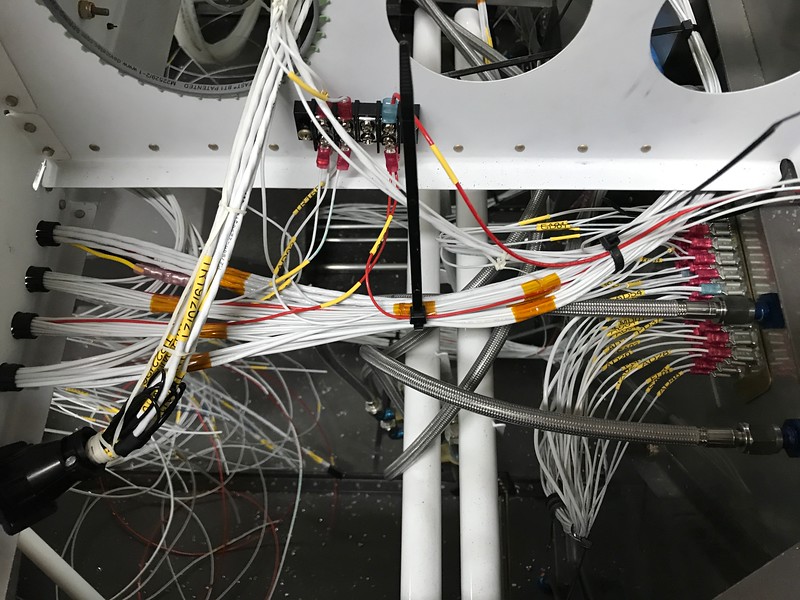
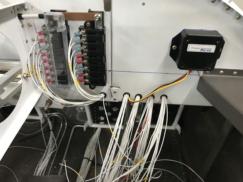
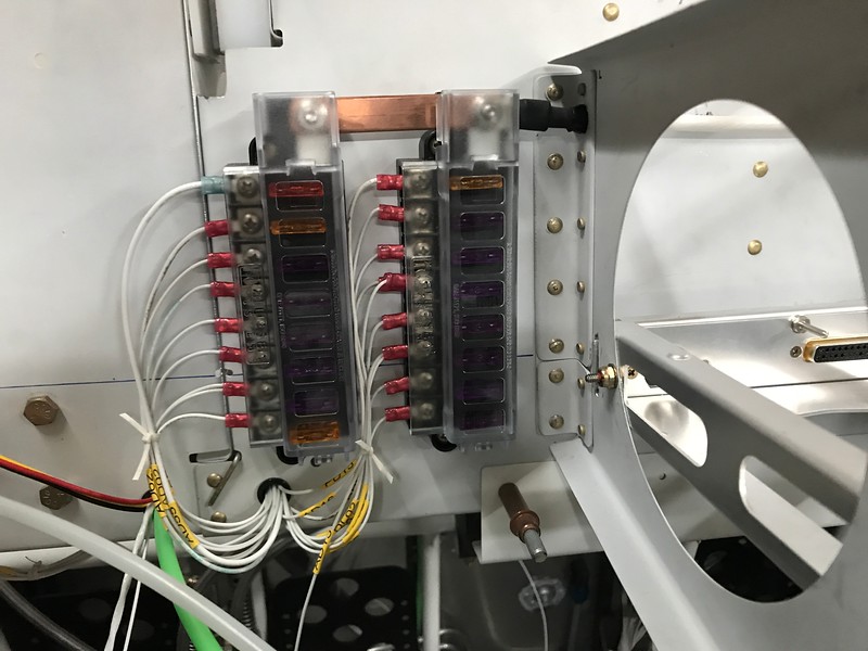
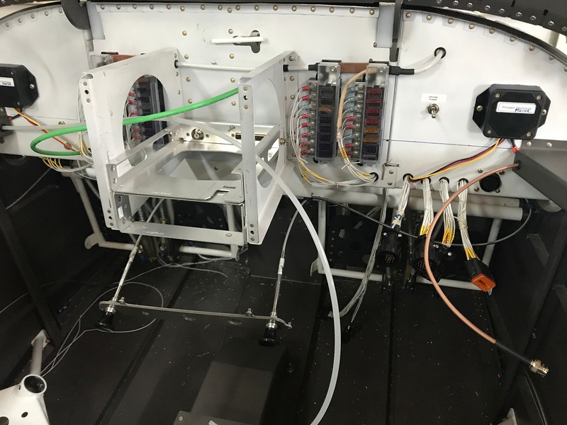
This thread is about all the cables going from the avionics bay to everywhere else. I made a list with conductor/size or manufacturer's designation. There's a lot. List is below

First question
I see OP-30 shows wire going up the tunnel then up the firewall tunnel and back. I've also seen wire going up the F-902 Bulkhead. What route did you take?

Second question
I have this document. Do I interpret the drawing correctly? One hole may be drilled in each bay? Potentially four holes total?

List. The ACM requires individual runs for the servos and ADAHRS so no hub.
Com,coax
Xponder,coax
ADSB,coax
Wing Tip left, 18/2 (Land/Taxi), 22/3 (Strobe/Pos)
Wing Tip right, "
Tail strobe, 22/2
Stall switch, 18/1
Sticks, ACM cable
Boost pump, 18/1 red, 18/1 Blk
Roll Servo, Dynon network cable
Pitch Servo, Dynon network cable
ADAHRS, Dynon network cable
Pitch Trim, Ray Allen cable
Roll Trim, Ray Allen cable
ELT, 22/3
 
Last edited:
Here's what I did. Not sure if it will help your particular case, but...

I divided my circuits up into:

A) Wires going to the panel
B) Wires going to the panel-side of the subpanel (left)
C) Wires going to the panel-side of the subpanel (right)
D) Wires going to the area between the subpanel and the firewall
E) Wires going to the forrest of tabs on the firewall

I ran B and D up the left side of the tunnel area and A, C and E up the right.


From there, E is done. Plug em into the forrest. A got divided up into connectors, and then A, B, and C ran forward through the subpanel.


D got connectors and went to a separate "shelf" between the subpanel and firewall.


B and C got routed to their various subpanel electronics.


Wires A went to connectors to allow the panel to be removable.


For the wires routed through the center section, I planned my avionics locations so that I could fit all the wires through Van's existing holes. I barely made it. I don't think I could even fit one more 22ga wire through the existing holes!
 
slight mod...

Hey Ryan,

When you get around to it, cut a piece of heatshrink of the correct size and place it over the exposed copper buss bars.

B
 
Hey Ryan,

When you get around to it, cut a piece of heatshrink of the correct size and place it over the exposed copper buss bars.

B

As soon as I posted those photos, I knew someone was going to point that out :) The VAF community catches everything! Already done, but good catch nonetheless.
 
Larry, I wrestled with the same question. I ran a few wires under each cabin fuse rail. But would try to avoid that again. I did the major paths down each side of the center two ribs, jump from outer to inner at the firewall/fuse turn on the floor, then back and spread at the spar.

Plan well on the area under the fuel pump and splitting wires at the spar. Better to plan to minimize cross overs between the spar and fuel pump. It got pretty tight in there.

I made one extra spar hole per the doc you posted. If in question, Vans can help, but the document did not seem to be ambiguous. Since there are two sides that need holes, (my memory is not clear on this) I made templates to see which forward spar holes matched better with the aft for my selection. Memory is bad, just check it.

The only thing I would recommend to run under/along the fuse rail is the static line so it won't have a low zone to collect water. The pitot routing through the spar was a challenge with short radius bends so resorted to heating, bending and chilling to freeze the shape so it routed like aluminum tubing. It is much easier.
 
Wiring my 6A

In response to the "first question"; almost everything electrical from the rear is running fwd under the baggage/seat floors then through the wing spar then through the floor tunnel and up the firewall and then back to the sub-panel, where the modules are mounted. The one exception is the fuel tank level sender wires that enter the fuselage near the tank leading edge just ahead of F902 (or F602 in my case) and run up F902 to the sub-panel.

The pitot and static tubes run under the side rail and connect to the Dynon ADAHRS that is in the tailcone and also to the steam gauge ASI that is in the panel. The AOA tube enters the fuselage under the seats, along with the wiring for the wing lights.

Philosophically, I'm aiming to hide all wiring and keep it out of harm's way and also trying to make it easy to access for maintenance and trouble shooting.
 
What is the thought on fuses on sub panel behind instrument panel. Access is not great. Obviously you would not do this during flight... just curious. Super clean nice installation. Well done. Thanks for sharing.

My thought process:

With fuses I am only worried about access on the ground, not in the air. If I believed access in the air was critical, I would have gone with circuit breakers. Whether or not access in the air really is critical is a separate discussion.

Because I built a tip-up, the subpanel provides ample access on the ground. If I built a slider I probably would have found a better spot for the fuses.
 
Wire routing details

Here is a bit more detail (PDF attached, click on the black shape to open) for how I'm routing the various lines to the sub-panel.

I was thinking about physically diverse paths for the Skyview network A&B wiring but that is going to be difficult to implement because of limited options for passing through the RV-6 wing spar.

This is still work-in-progress.
 

Attachments

  • Pitot Static AOA Wiring runs.pdf
    121.9 KB · Views: 100
Wire path

Thanks. The comments are helpful.
It seems this is one of those "do whatever you must" sort of tasks.

Still no answer to this question.

I have this document. Do I interpret the drawing correctly? One hole may be drilled in each bay? Potentially four holes total?

I am going to try an get by without drilling any.
 
Thanks. The comments are helpful.
It seems this is one of those "do whatever you must" sort of tasks.

Still no answer to this question.

I have this document. Do I interpret the drawing correctly? One hole may be drilled in each bay? Potentially four holes total?

I am going to try a get by without drilling any.

That was my interpretation, one hole per template in the corresponding bay, for 4 holes total.

With pitot / AoA tubing and wires, it was very tight getting all my wires and tubing past the spar. This dilemma drove me to place the transponder and comm antennas forward of the spar.
 
Back
Top