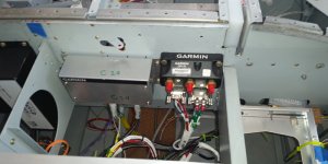
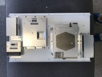
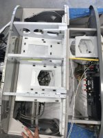
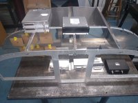
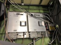
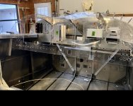
RV-10. I originally mounted the GSU25 on the subpanel. Had AHRS issues on and off for months. Worked with Garmin to resolve. Got really good at recalibrating the compass

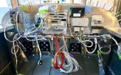
. Eventually got help from an RV10 owner from Australia who helped identify the problem as vibration. Moved the GSU25 to the back of the center GDU460. Been rock solid for almost a year.
Hi Larry
That was me
Ill try not to war and peace on this, but I think Garmin has been less than forthcoming with GSU issues and could save people A LOT of grief with some updated guidance.
Now that I see that more people coming out of the woodwork with same problem I should speak up.
Garmin repeatedly told me that it was a CanBus issue from the get go. I was skeptical as I have wired many and I think my work is of good quality. Each node was tested during construction in every install I've done. There were nil network errors, and swapping devices around on the bus made no difference.
I got 4 different support people cut and paste me the "troubleshooting guide" which was less than insightful.
Reluctantly, I rewired my entire RV10 CanBus - node by node - recalibrating each time - which made no difference. At this point I started getting cranky.
After expressing my displeasure with the support I effectively got left to my own devices. Maybe the timezone is an issue. I don't know. Im on good terms with the Australian people.
The penny dropped after I investgated the "acoustic noise vibration" SB some more.
Anecdotally, Garmin changed suppliers for some of the MEMS bits in the GSUs at some stage and they were "different". Maybe more sensitive in some modes. Carbon Cubs with them mounted on the wing spar were getting "rain" induced "acoustic vibration" as were RV12s with them on the floor down the back. There were various workarounds. The SB is worth a read. Eventually new GSUs was the solution I believe.
With this in mind, I went back and regressed the vibration data against RPM and power, and sure enough, as Ryan found, it was clearly correlated to various power/RPM combos.
It was from the very first flight! Then I set about moving them around, stiffening the subpanel etc until the only place it resolved was on the back of the GDU.
Larrys files exhibited similar RPM/Power v Vibration correlation.
Maybe the screen (and perhaps the whole panel) serves as an inertial mass?
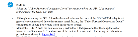
Yes, this definitely crossed my mind. I think the original "not on the back of the GDU" guidance could have been a result of aircraft that had shock mounted panels to isolate mechanical instruments.
In my mind, an aluminum airplane with a lycoming on the front is going to have plenty of vibration (acoustic or otherwise) no matter where you put the thing.
In short, having to move the thing around the airframe until it works is less than ideal. It seems clear now that in many aircraft, the only place current GSU25s dont suffer from vibration induced degraded performance, is the very same (and only) place Garmin tells you NOT to mount it.
This is worth addressing.


 .
.