What's new
Van's Air Force

Don't miss anything! Register now for full access to the definitive RV support community.

Oil Cooler on Engine Mount

Freemasm

Well Known Member
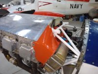
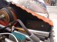
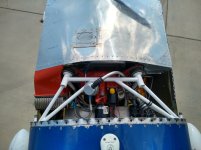
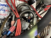
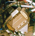
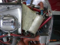
This was a drift/response to the thread “yet another oil cooler thread”. My apologies if this has already been presented/discussed/debated. Trying to avoid the known baffle crack contributors. Also, my cowl is much tighter than Vans so it would push the cooler behind #4 to some degree. So, remote mount was my best option approach. Settled on an engine mount, mount. Not saying it’s best or will work for everyone but it solved some problems for me without having to rivet on the FW. The burden (for me) was shifted to composite fab. Still not good at it but getting better. Oil cooler louver, should it be needed, will be an easy add.

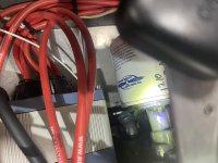
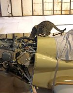
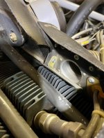
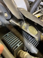
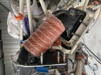
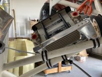
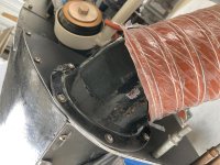
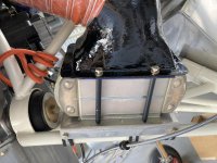
@Wirejock Larry, a follow up to you. Form and fit are verified. Function verification is still a ways off. Two of four pix got rotated but you get the idea.
 

Attachments

  • IMG_8438.jpg
    IMG_8438.jpg
    444.7 KB · Views: 225
  • IMG_8439.jpg
    IMG_8439.jpg
    319.1 KB · Views: 222
  • IMG_8440.jpg
    IMG_8440.jpg
    376.9 KB · Views: 145
  • IMG_8441.jpg
    IMG_8441.jpg
    370.1 KB · Views: 202
Last edited:
Since this is generally about techniques to building, let me throw out another option that has worked well for me on several airplanes:

It seems that a baffle mount made of glass rather than aluminum appears to solve the baffle cracking issues. Let me offer up the latest example from my Rocket. I have chased cracks in aluminum on many airplanes (including this one) but when I went to this huge cooler I had to get creative on the location to get it to fit. I hung it in space and filled in the gaps with manila file folder stock and masking tape. Once it looked good, I glassed it over. Looks pretty good and has been flawless in service.

Just another option to consider.
 

Attachments

  • cooler.jpg
    cooler.jpg
    54.1 KB · Views: 293
Mike,
Are you saying that your oil cooler is suspended only by that composite duct? Can you supply any more photos please?

Charlie
 
Since this is generally about techniques to building, let me throw out another option that has worked well for me on several airplanes:

It seems that a baffle mount made of glass rather than aluminum appears to solve the baffle cracking issues. Let me offer up the latest example from my Rocket. I have chased cracks in aluminum on many airplanes (including this one) but when I went to this huge cooler I had to get creative on the location to get it to fit. I hung it in space and filled in the gaps with manila file folder stock and masking tape. Once it looked good, I glassed it over. Looks pretty good and has been flawless in service.

Just another option to consider.

I not only considered such but actually started fab’ing it. Cantilevering the cooler weight away from the baffle was my first worry. Attaching to the side baffle solves half of that worry. Angling both down and in (needed here) allows air extraction from the highest, widest point. Clever. You still have extraction below the cyl fins; my biggest worry as previously mentioned. If you’ve validated good cylinder temps on a notoriously hot airframe/engine combo in the high dessert, it should be good most anywhere. I would have lost that bet.

Still guessing my approach may ultimately have less worries than yours though you’ve validated your approach and I haven’t. Of course, there probably isn’t room behind a 6 cylinder beast.

Thx for sharing
 
Last edited:
Yes, the cooler is hung entirely by the fiberglass duct. No, the air inlet does not extend below the top of the fins. The air inlet is as wide as I could get it given the real estate, but still represents a bit less area than the face of the cooler. However, given you lose about 30% in fins and tubes, the effective air path through the cooler is a better match for my inlet. I went up one size on this cooler to try deal with my piston jets. I also removed the vernatherm and run the bypass piston year round. I have no cooling issues in even the hottest flying. In fact, I reduced the size of my oil lines to #6 to try "throttle" the flow. And concerning my CHT's - generally within 15 degrees hottest to coldest. (typically about 370)
 

Attachments

  • cooler fins.jpg
    cooler fins.jpg
    318 KB · Views: 170
  • Plenum above.jpg
    Plenum above.jpg
    312 KB · Views: 164
Last edited:
@ Mr, Robinson. Didn't notice it was mounted with headers on the sides. I was afraid to try that as I didn't want to rob air past the head/into the combustion zone of the cylinder. Looks like You invalidated that fear of mine as well.

@ Mr. Paule. I have more 4" SCAT. The one in the pic is the near-exact length one I used to align the outlets on the foam mold cores I made for the two ducts. That actually worked well. The SCAT has no detectable bend. Don't ask me why that was important to me. The current overlaps are smaller than the clamps that will go on.
 
@ Mr, Robinson. Didn't notice it was mounted with headers on the sides. I was afraid to try that as I didn't want to rob air past the head/into the combustion zone of the cylinder. Looks like You invalidated that fear of mine as well...

I've read the above a dozen times and I'm still not quite tracking...

The header (tanks) of the cooler are mounted top and bottom, not on the sides.... But in any case, not sure how that changes airflow?
 
My apologies. I looked again on a laptop vs. my phone screen and can see a lot more detail. Looking at your first pic, it is indeed a vertical mount. The second set of pix was the basis of my comment/what threw me off. Man, that's a big heat exchanger and a wide extraction. To my point, I was afraid to take air from a point that was behind the cylinder combustion zone. The "left and as high as possible" approach and subsequent instructions on the Vans drawings reinforced this concern to me. In my mind, your approach surely would have caused a high/uneven cyl 4 (or 6) temp.

As mentioned, you've validated your approach in a tough engine/airframe combo in high dessert conditions. Again, I would have lost that bet.

Much thx for sharing.
 
Hey tool builder, can you take a look at the pictures if you have a minute. My rocket/540 c4b5 cruises around 196 degs F. Top of climb in the summer to 10k can get to 230 degs, but comes back down quickly once level. It has never red lined and does warm up a little in the pattern. The plane was built by harmon and I would assume he installed the oil cooler connections as they are today today, but can not verify it. My oil cooler, 2006x, is plumbed different than anything else I can find. The return is in the stock location, but the feed line is actually attached where the oil plunger hole would normally be and the normal oil cooler feed hole is capped. I can only assume this was for clearance in the fire wall. Do you have any idea what the comparable flow rate would be with the feed line attached as shown versus the stock location? My cht’s are great, rarely get about 380 in climb and cruise normally runs around 350. Really appreciate your input.
 

Attachments

  • IMG_5896.jpg
    IMG_5896.jpg
    420 KB · Views: 140
  • IMG_5897.jpg
    IMG_5897.jpg
    278.4 KB · Views: 113
  • IMG_5898.jpg
    IMG_5898.jpg
    189.5 KB · Views: 102
Last edited:
My oil cooler, 2006x, is plumbed different than anything else I can find. The return is in the stock location, but the feed line is actually attached where the oil plunger hole would normally be and the normal oil cooler feed hole is capped.

It's fine.
.
 

Attachments

  • Lycoming Oil Cooler Connections.jpg
    Lycoming Oil Cooler Connections.jpg
    97.3 KB · Views: 146
My apologies. I looked again on a laptop vs. my phone screen and can see a lot more detail. Looking at your first pic, it is indeed a vertical mount. The second set of pix was the basis of my comment/what threw me off. Man, that's a big heat exchanger and a wide extraction. To my point, I was afraid to take air from a point that was behind the cylinder combustion zone. The "left and as high as possible" approach and subsequent instructions on the Vans drawings reinforced this concern to me. In my mind, your approach surely would have caused a high/uneven cyl 4 (or 6) temp.

As mentioned, you've validated your approach in a tough engine/airframe combo in high dessert conditions. Again, I would have lost that bet.

Much thx for sharing.

We might be talking past each other here but I want everyone to understand that I am not pulling ANY air from "behind" the #6 cylinder. The opening is entirely above the fins and there is a full baffle wall running all the way down the fins. In fact, the "wall" is not only full height, but wraps around the top of the head and terminates adjacent to the rear pushrod tube. The curved "wrap" portion serves as a smooth transition into the oil cooler plenum (top/back side) as well as a diverter shroud for the head fins (lower/front side). The upper deck pressure and volume is such that #6 still gets plenty of flow down that journey through the fins AND the oil cooler plenum also gets its share. No "theft" of air involved because there is plenty of air for both consumers, and there is a physical barrier keeping them individually organized.
 
Last edited:
It's fine.
.

Yep. I have one of those galley plugs with a #6 AN nipple on it in my scrounge (it came off my HIO-360). Was going to use it for the same reason - packaging ease - but thought my use of the plunger would complicate that plan. Went to the primary location instead.
 
Scott, it might be worth lengthening the Scat hose to give the engine a bit more room to move around.

Dave

Dave I have my plenum inlets about 3/16" from the cowl mounted inlet ring, maybe less. It has not touched. Dave Anders has his oil cooler with a small gap to the hard parts too. Both are in planes perpendicular to the crank, and the gaps are axial. You may be right about Scott's, as it addresses the radial motion of the engine. My plenum is pretty close to the cowl and the radial motion is about 5/16" to 1/2" max at the top corners of the baffle - a dimension to target. A clamp on the engine side might be all that is needed.
 
A different view of extraction approach for the engine mount oil cooler. Different than Toobuilder/Mr Robinson whose approach has been validated. As high as I could get (IAW Vans drawing note) and not behind the combustion part of the cylinder; a fear (mine) that might be unnecessary per the aforementioned’s experience. The extraction barely fits this application. Should have more leeway for a straight up Vans build.

Effectiveness will hopefully be measured before I’m dead.

Man I wish I knew why only some of the attached pix get rotated.
 

Attachments

  • IMG_8463.jpg
    IMG_8463.jpg
    368.8 KB · Views: 63
  • IMG_8464.jpg
    IMG_8464.jpg
    330.6 KB · Views: 67
A different view of extraction approach for the engine mount oil cooler...

I think you would benefit greatly with the simple addition of a bellmouth on the inlet to that duct. Probably something COTS or close available or even make a one off out of glass. Would not take much... Just break that sharp lip at the entrance.
 
This was a drift/response to the thread “yet another oil cooler thread”. Trying to avoid the known baffle crack contributors. Also, my cowl is much tighter than Vans so it would push the cooler behind #4 to some degree. So, remote mount was my best option approach. Settled on an engine mount, mount.

I would watch your suspension system VERY closely. The weight of that cooler with the added G forces of flight might not be supported enough by Adel clamps. And the attach points of those clamps do not spread the forces far enough around the plate the cooler sits on. Not sure how much a cooler full of oil with attached hoses weighs but it is enough to be well-supported.

Here are pictures of mine. I made clamps out of steel tubing to suspend the cooler on the engine mount. I have seen WAY too many baffle-mounted coolers that have cracked the baffle. That's my IA on the boot cowl. I have close-ups somewhere but can't find them. I'll post them when I can find them. I have a 2 inch intake off the baffle and still have to close it off. Plenty of air flow....
 

Attachments

  • IMG_7470acS.jpg
    IMG_7470acS.jpg
    338.3 KB · Views: 80
  • img.838.jpg
    img.838.jpg
    111.6 KB · Views: 81
  • img.834.jpg
    img.834.jpg
    114.4 KB · Views: 59
I think you would benefit greatly with the simple addition of a bellmouth on the inlet to that duct. Probably something COTS or close available or even make a one off out of glass. Would not take much... Just break that sharp lip at the entrance.

Yes/not sure. Of course it would keep vortices from being shed but I’m not convinced I’d need it here. The majority of loss through the cooler, proper; thus, it should have plenty of available flow. Are you thinking said vortices will cause uneven flow through the cooler area? I considered it but don’t have a feel for the turbulation from the SCAT itself. That itself can’t be good so any mods to the extraction would wait until validation.

I would watch your suspension system VERY closely. The weight of that cooler with the added G forces of flight might not be supported enough by Adel clamps. And the attach points of those clamps do not spread the forces far enough around the plate the cooler sits on. Not sure how much a cooler full of oil with attached hoses weighs but it is enough to be well-supported.

Here are pictures of mine. I made clamps out of steel tubing to suspend the cooler on the engine mount. I have seen WAY too many baffle-mounted coolers that have cracked the baffle. That's my IA on the boot cowl. I have close-ups somewhere but can't find them. I'll post them when I can find them. I have a 2 inch intake off the baffle and still have to close it off. Plenty of air flow....

The Adele are vertical so more compression than bending loads. I can put about 35 lbf with very little deflection. Can easily but some material between the frame and mount that would take basically all of the positive loading and the clamps merely hold the assemblies relative position. The entire ultimately needs validation. I threw it out to the world as an option to consider that will avoid known baffle cracking and eliminate FW riveting which sucks to me. If I encounter issues, I won’t hide them.
 
Oil cooler mount

The Adele are vertical so more compression than bending loads. I can put about 35 lbf with very little deflection. Can easily but some material between the frame and mount that would take basically all of the positive loading and the clamps merely hold the assemblies relative position. The entire ultimately needs validation. I threw it out to the world as an option to consider that will avoid known baffle cracking and eliminate FW riveting which sucks to me. If I encounter issues, I won’t hide them.

I think vibratory stresses would be more of a problem than torque/compression. Just something to watch.

Not sure if vortices through the SCAT or other parts are a problem. Again, mine is a 2 inch and, if I don't partially block it off (and it has an outflow gate), oil temps don't want to get up there and stay. RV-4s are much better at cooling than other designs, however....:cool:
 

Attachments

  • img709acs5.jpg
    img709acs5.jpg
    1 MB · Views: 63
Last edited:
Yes/not sure. Of course it would keep vortices from being shed but I’m not convinced I’d need it here. The majority of loss through the cooler, proper; thus, it should have plenty of available flow. Are you thinking said vortices will cause uneven flow through the cooler area? I considered it but don’t have a feel for the turbulation from the SCAT itself. That itself can’t be good so any mods to the extraction would wait until validation...

The sharp lip creates localized turbulence that "in effect" makes the duct smaller. Whether your particular duct is oversized enough to mask this feature remains to be seen, but it DOES exist. Sharp transitions like this are seen often and usually work, but they are almost always creating a loss that would not otherwise exist.

If your cooling turns out to be on the marginal side, the first experiment should be an inlet radius, IMHO.
 
I think vibratory stresses would be more of a problem than torque/compression. Just something to watch.

Not sure if vortices through the SCAT or other parts are a problem. Again, mine is a 2 inch and, if I don't partially block it off (and it has an outflow gate), oil temps don't want to get up there and stay. RV-4s are much better at cooling than other designs, however....:cool:

When you get a chance - change out those nylock nuts (AN965) for steel lock nuts (MS21042)
 
3k hours on this one (my Super 8) mounted to engine mount. Duct is not attached to baffle. Just some cloth anti chafe tape between them. I have never done anything to this installation what so ever. I am unable to get my temps above 220 in any configuration. Most of my departures are 0 to 10k' zoom climb. I have to block off the inlet to the cooler in the winter.
More pics here.
 

Attachments

  • s8engine%20010.jpg
    s8engine%20010.jpg
    1.2 MB · Views: 71
Nuts......The nuts!

When you get a chance - change out those nylock nuts (AN965) for steel lock nuts (MS21042)

Good eye! ;) These pictures were taken quite a few years ago. I was waiting for the MS21042 to come from ACS and put those there "temporarily" and promptly forgot about them. They have since been changed! It was one of those "oh, ****" moments when I saw them later during a condition inspection! They were all still tight when I replaced them but didn't belong there!:)
 
Back
Top