I recently built this extremely high-tech, fully digital, solar-powered tuft jig for some stall testing:
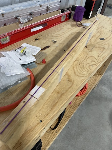
I scored the top of the 2x4 with a miter saw, and held the yarn with two fingers whilst slicing with a razor blade...used standard blue tape to lay out the tuft lines:
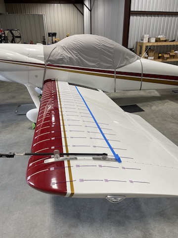
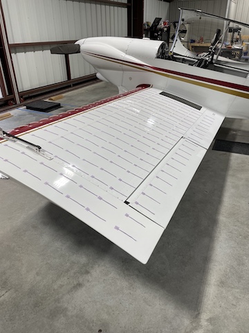
And used purple "no mar" Scotch tape to hold the individual tufts in place:
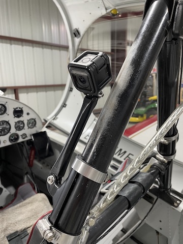
Built a new mount to raise the oblique camera above the canopy skirt to improve the field of view of the tufts during flight:
The purpose of this drill is to document separation behavior when flying near the stall and stalled. The constant thickness, no-twist, no-taper RV planform tends to stall "all at once." If the airplane is in a gliding turn (say, trying to maneuver after a loss of power during initial climb phase), this breakdown in lateral stability (fancy way of saying "stall") manifests itself as a sudden wing drop. If you plot AOA and airspeed margin (how close the the aerodynamic limit you are) in a gliding turn at the edge of the envelope, it looks like this:
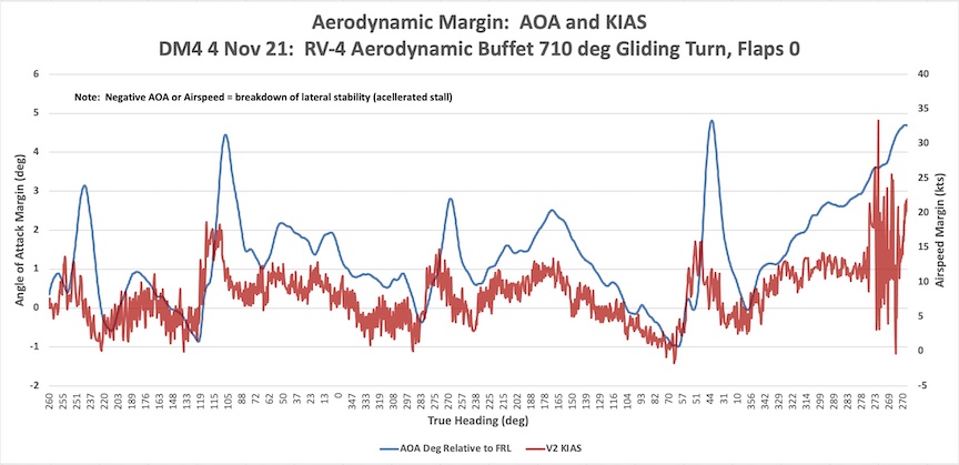
The valleys in the airspeed and AOA are actual stall (wing drop) where you can see the margin (difference between actual speed and AOA and stall speed and AOA) is zero.
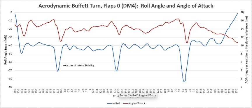
Here's another plot of the same maneuver showing angle of bank (roll) and AOA. Note that as the airplane stalls, sudden uncommanded roll (wing drop) occurs:
Fly safe,
Vac
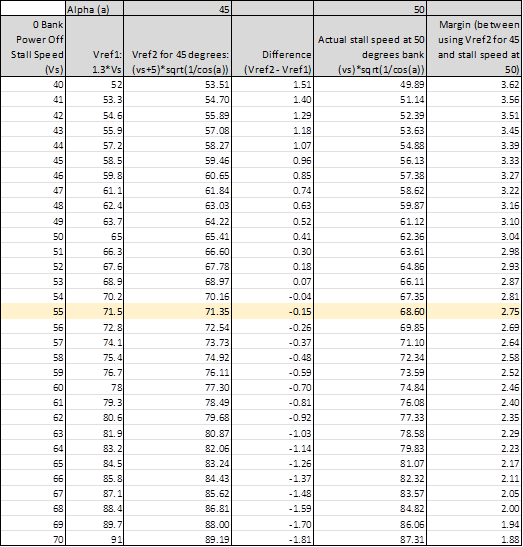
P.S. The indicated stall speed increases as a function of the square root of G load. A 45 degree banked gliding turn in the RV-4 averages 1.3 G's. Assuming you want a safety buffer, you can multiply indicated stall speed by the square root of 1.5 to determine stall IAS during that maneuver. Keep in mind, stall IAS will vary with gross weight. Easier for us mathematically challenged types to reference AOA when we are slower than corner velocity/maneuvering speed if the objective is to avoid the aerodynamic limit.
I scored the top of the 2x4 with a miter saw, and held the yarn with two fingers whilst slicing with a razor blade...used standard blue tape to lay out the tuft lines:
And used purple "no mar" Scotch tape to hold the individual tufts in place:
Built a new mount to raise the oblique camera above the canopy skirt to improve the field of view of the tufts during flight:
The purpose of this drill is to document separation behavior when flying near the stall and stalled. The constant thickness, no-twist, no-taper RV planform tends to stall "all at once." If the airplane is in a gliding turn (say, trying to maneuver after a loss of power during initial climb phase), this breakdown in lateral stability (fancy way of saying "stall") manifests itself as a sudden wing drop. If you plot AOA and airspeed margin (how close the the aerodynamic limit you are) in a gliding turn at the edge of the envelope, it looks like this:
The valleys in the airspeed and AOA are actual stall (wing drop) where you can see the margin (difference between actual speed and AOA and stall speed and AOA) is zero.
Here's another plot of the same maneuver showing angle of bank (roll) and AOA. Note that as the airplane stalls, sudden uncommanded roll (wing drop) occurs:
Fly safe,
Vac
P.S. The indicated stall speed increases as a function of the square root of G load. A 45 degree banked gliding turn in the RV-4 averages 1.3 G's. Assuming you want a safety buffer, you can multiply indicated stall speed by the square root of 1.5 to determine stall IAS during that maneuver. Keep in mind, stall IAS will vary with gross weight. Easier for us mathematically challenged types to reference AOA when we are slower than corner velocity/maneuvering speed if the objective is to avoid the aerodynamic limit.
Last edited:
") ). I found this "purple" tape in the aviation isle at my local Ace. Does a good job and no issues with the paint. I did learn it's probably a good idea to dip the bitter end of the tuft in some Elmer's or something similar to keep it from unraveling...20/20 hindsight, of course.
). I found this "purple" tape in the aviation isle at my local Ace. Does a good job and no issues with the paint. I did learn it's probably a good idea to dip the bitter end of the tuft in some Elmer's or something similar to keep it from unraveling...20/20 hindsight, of course.