David Paule
Well Known Member
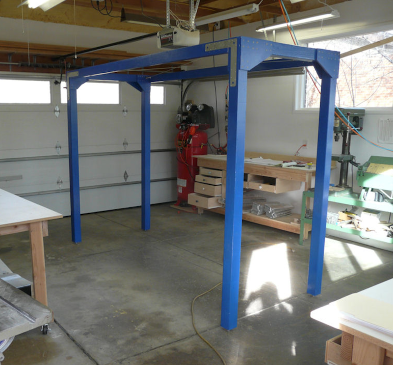
The shop is ready. I'll be building this RV-3B in my garage, a smallish two-car garage attached to my older tract home in a cheap part of town. The kit's boxes haven't arrived yet, so at this stage all I'm doing is reporting that the shop is ready.
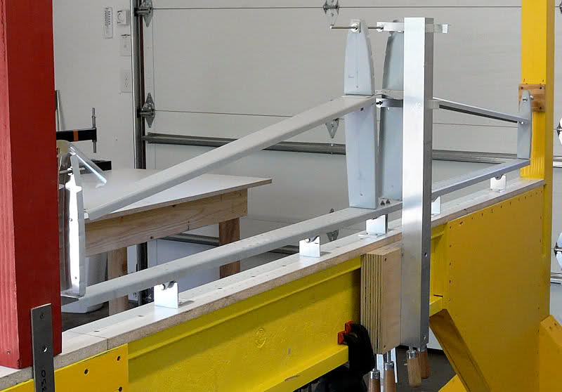
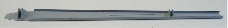
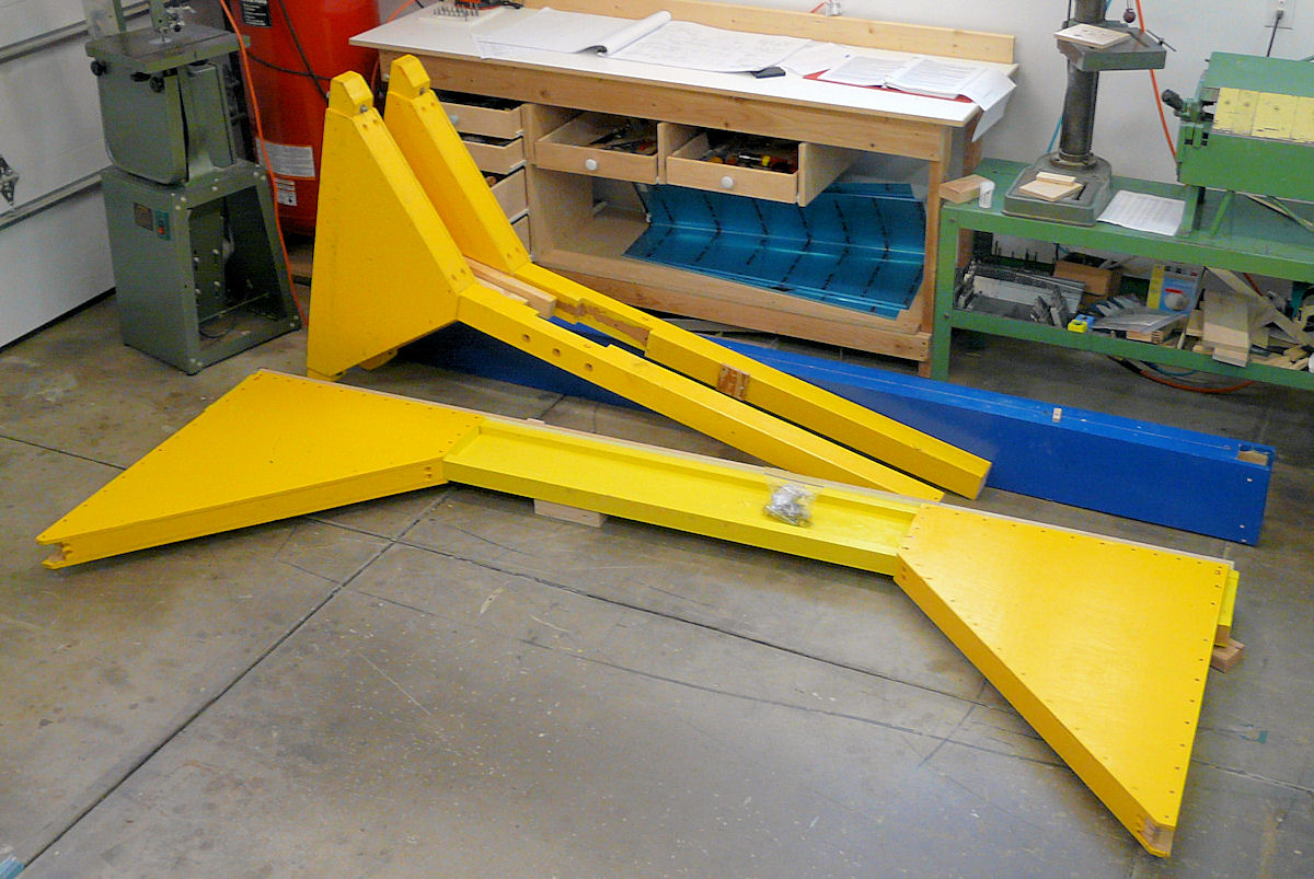
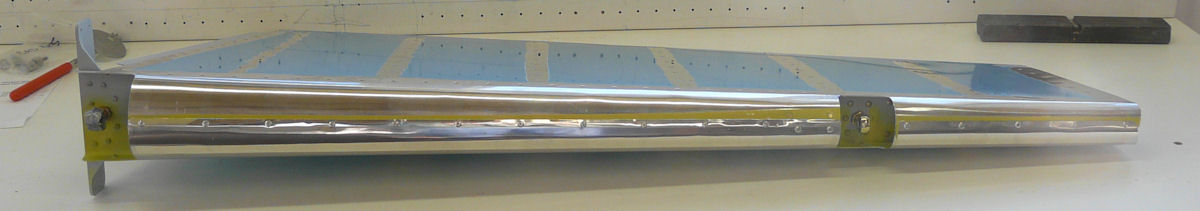
The empennage jig is from Rod Woodard, in Loveland, CO. It was originally made by Walt Ellwood, I think, and disassembled, fits in my pickup truck. It's quite stiff and is one worry crossed off the list - thanks, Rod!.
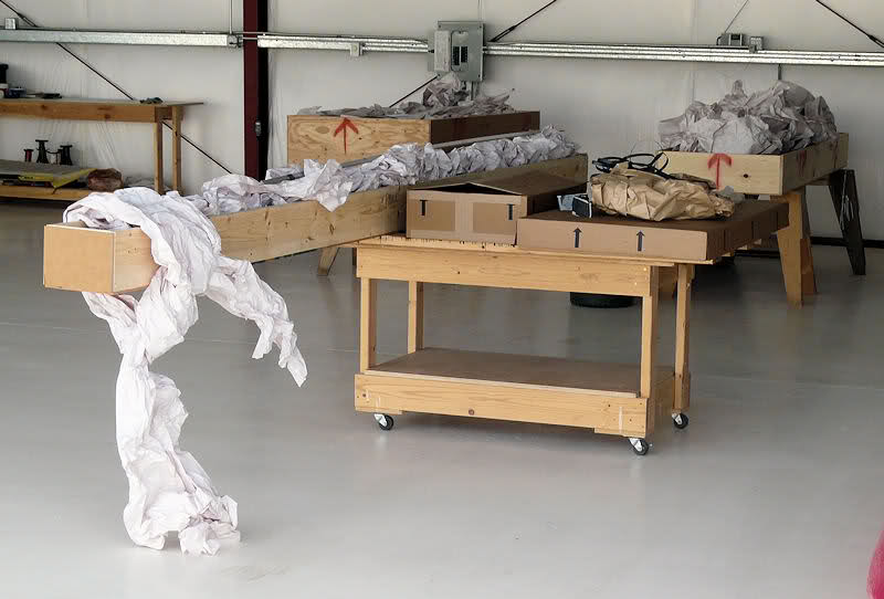
I made three new work tables for this project. The design is considerably easier to built than the EAA table, and so far I've made seven of these. They're good. For these three, I used up some surplus plywood to make the drawers, since I don't have floor space for a roll-away tool cabinet.
The tables are white melamine-faced particle board that was previously used for a friend's aluminum motorglider project. They've put one airplane in the air, and I'm counting on them to do another. The smooth white surface is easier to use and to clean than particle board or plywood.
In the first photo, we're looking south. The windows were added in anticipation of this project. They are shaded by the deciduous tree that shades the patio. In the summer it doesn't get too hot, and in the winter a lot of light comes in.
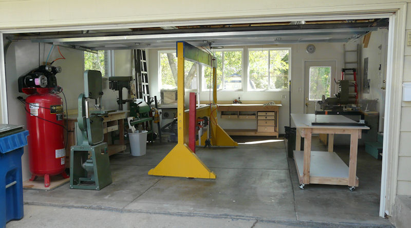
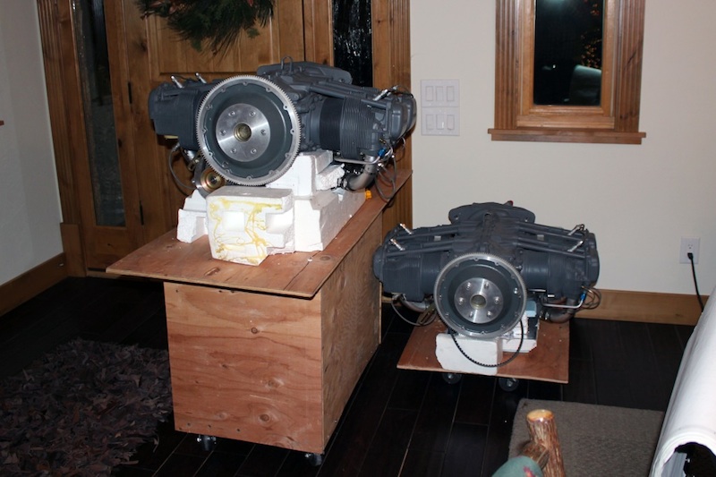
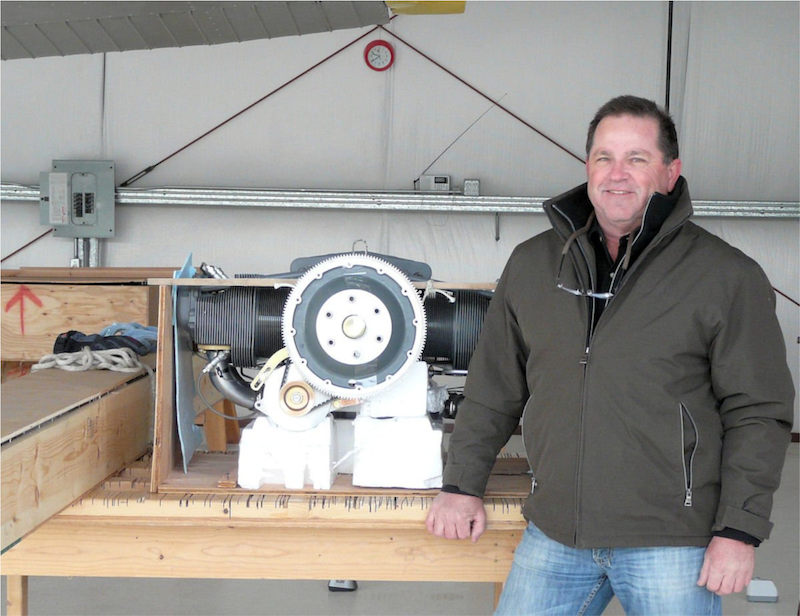
The obscure machine in the right corner is a large belt/disc sander. It might be too big; we'll see. It's setting on a crate that holds the original engine to my Cessna Skywagon.
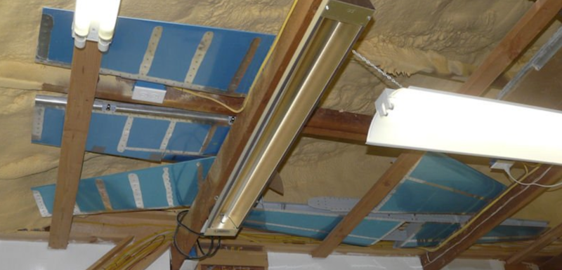
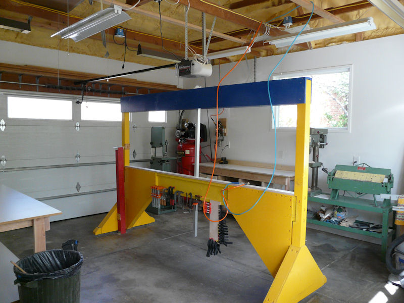
In the next photo you can see the underside of the garage roof. I had it foamed. The vendor sprayed about 6" of insulating foam up there, for a tight, leak-proof, insulated ceiling. Yes, it's got that special fireproof paint, too.
The walls are well-insulated with cotton batting and then dry-walled. The contractor ran electricity around the garage at the right height so the outlets would be above the work tables and below the windows. And of course, the garage door is insulated, too.
The garage stays between about 40 deg. and 80 deg. with no cooling or heating. I have electric radiant heaters above on thermostats, with about 12 kw heat output (40,000 btu/hr if you prefer these units). For cooling, I get cooled air from the house if necessary. The house has a powerful swamp cooler on a thermostat. It's an excellent way to do it if your climate is dry enough.
Real briefly, I want to mention Dave Dooley, who gave me the work table tops and a plethora of hand tools; Rod Woodard, who gave me the empennage jig; Paul Gassaway, who gave me the drill press 35 years ago; Dan Pierce, who converted the garage into a shop; and Leo Kallan, who gave me the sander. While I'm at it, DR, who hosts this site (have you donated yet this year?); and Paul and Louise, who got me thinking about the RV-3 in the first place. Friends all, and some of them I haven't even met yet.
Thanks, everyone!
Alternate hosting here and here.
Dave
The empennage jig is from Rod Woodard, in Loveland, CO. It was originally made by Walt Ellwood, I think, and disassembled, fits in my pickup truck. It's quite stiff and is one worry crossed off the list - thanks, Rod!.
I made three new work tables for this project. The design is considerably easier to built than the EAA table, and so far I've made seven of these. They're good. For these three, I used up some surplus plywood to make the drawers, since I don't have floor space for a roll-away tool cabinet.
The tables are white melamine-faced particle board that was previously used for a friend's aluminum motorglider project. They've put one airplane in the air, and I'm counting on them to do another. The smooth white surface is easier to use and to clean than particle board or plywood.
In the first photo, we're looking south. The windows were added in anticipation of this project. They are shaded by the deciduous tree that shades the patio. In the summer it doesn't get too hot, and in the winter a lot of light comes in.
The obscure machine in the right corner is a large belt/disc sander. It might be too big; we'll see. It's setting on a crate that holds the original engine to my Cessna Skywagon.
In the next photo you can see the underside of the garage roof. I had it foamed. The vendor sprayed about 6" of insulating foam up there, for a tight, leak-proof, insulated ceiling. Yes, it's got that special fireproof paint, too.
The walls are well-insulated with cotton batting and then dry-walled. The contractor ran electricity around the garage at the right height so the outlets would be above the work tables and below the windows. And of course, the garage door is insulated, too.
The garage stays between about 40 deg. and 80 deg. with no cooling or heating. I have electric radiant heaters above on thermostats, with about 12 kw heat output (40,000 btu/hr if you prefer these units). For cooling, I get cooled air from the house if necessary. The house has a powerful swamp cooler on a thermostat. It's an excellent way to do it if your climate is dry enough.
Real briefly, I want to mention Dave Dooley, who gave me the work table tops and a plethora of hand tools; Rod Woodard, who gave me the empennage jig; Paul Gassaway, who gave me the drill press 35 years ago; Dan Pierce, who converted the garage into a shop; and Leo Kallan, who gave me the sander. While I'm at it, DR, who hosts this site (have you donated yet this year?); and Paul and Louise, who got me thinking about the RV-3 in the first place. Friends all, and some of them I haven't even met yet.
Thanks, everyone!
Alternate hosting here and here.
Dave
Last edited:
")