Desert Rat

Well Known Member
On the G3X I have my ammeter shunt set up to show the load on the main buss. It appears to be reading the correct number of amps, but it's a negative number. I guess that in a way this makes sense as it's the number of amps the load is sucking up. Nonetheless, it just seems backward to me.

I've already gone into the config menu without finding anything applicable. I also tried swapping the two wires to the shunt, which just resulted in a red X for the ammeter display.

Is there any way to get rid of this minus sign other than just changing the location of the shunt so that it's measuring something else?
 
So - Do you have a Shunt type sensor as delivered with Garmin engine sensor kit or a Hall Effect sensor ?
I surmise the sensor is installed to measure either battery discharge or battery charge (as opposed to a load meter install).
Does the meter show positive when engine running & battery charging ?
The more info you share the better....
I included an excerpt from G3x install re ammeter sensors & installs
Your swapping shunt leads "should" have worked if it was indeed a shunt.
Good luck.
 

Attachments

  • Pages from G3X IM 190-01115-01_AU.pdf
    258.6 KB · Views: 7
Last edited:
So - Do you have a Shunt type sensor as delivered with Garmin engine sensor kit or a Hall Effect sensor ?
I surmise the sensor is installed to measure either battery discharge or battery charge (as opposed to a load meter install).
Does the meter show positive when engine running & battery charging ?
The more info you share the better....
I included an excerpt from G3x install re ammeter sensors & installs
Your swapping shunt leads "should" have worked if it was indeed a shunt.
Good luck.
It's the Garmin shunt. It's wired downstream of an ANR fuse between the battery contactor and the main buss. My intent in wiring it this way is to measure the total load on the buss. The plane isn't flying yet, but it appears to be functioning as I would expect, other than the numbers are displaying as a negative. i.e. when the screens and avionics are on its indicating about -7 amps, when I turn on lights etc the number goes "up" to -10, -12, something like that.

What I've just described happens regardless of whether it's running off of the ship's battery or an external power supply.

Here's the best picture I could find at the moment.
 

Attachments

  • Unknown.jpeg
    Unknown.jpeg
    15.1 KB · Views: 40
It's the Garmin shunt. It's wired downstream of an ANR fuse between the battery contactor and the main buss. My intent in wiring it this way is to measure the total load on the buss. The plane isn't flying yet, but it appears to be functioning as I would expect, other than the numbers are displaying as a negative. i.e. when the screens and avionics are on its indicating about -7 amps, when I turn on lights etc the number goes "up" to -10, -12, something like that.

What I've just described happens regardless of whether it's running off of the ship's battery or an external power supply.

Here's the best picture I could find at the moment.
Unable to glean much from picture... however sounds like a negative is correct when running things off ships battery.
Next experiment - can you connect a ground power supply (not a battery charger) onto lead coming from alternator (disconnect alt 1st) to simulate charging from a running alternator - reading should go positive if everything is wired & operating properly. Master should be ON and battery should indeed be charging.
 
On the G3X I have my ammeter shunt set up to show the load on the main buss. It appears to be reading the correct number of amps, but it's a negative number. I guess that in a way this makes sense as it's the number of amps the load is sucking up. Nonetheless, it just seems backward to me.

I've already gone into the config menu without finding anything applicable. I also tried swapping the two wires to the shunt, which just resulted in a red X for the ammeter display.

Is there any way to get rid of this minus sign other than just changing the location of the shunt so that it's measuring something else?
If I remember correctly, on the shunt, you have two small wire terminals to attach the wires sending readings back to the device.
it may be as simple as reversing those two wires.
good luck
 
Just reverse the two wires. The G3X is measuring the voltage across the shunt. It's a differential measurement meaning it measures the difference in voltage between the two point. Reverse the wires and you will be subtracting B-A versus A-B.
 
guys- I already tried reversing the wires and got red X thru the ammeter tape. I just unscrewed th screw-together inline fuse housings and swapped them. I suppose it's possible I didn't get one of them seated properly and had an open, so I'll try it again tomorrow and we'll know for sure.
 
Can you post an electrical schematic diagram showing the battery, battery contactor, fuse, shunt, main bus, alternator, and power supply connection?
 
Can you post an electrical schematic diagram showing the battery, battery contactor, fuse, shunt, main bus, alternator, and power supply connection?
I'll get a picture of the whole layout tomorrow if swapping the leads (round two) doesn't work
 
The most common spot to install the shunt is between the alternator and master solenoid, this should normally be a positive value showing the output flow towards the battery and buss load. If the ammeter shows a negative value here, you have a charging problem.

If you place the shunt between the master solenoid and battery, it could show either positive ( charging the battery), or negative (draining the battery). A negative value would be normal if the engine is not running. If you got a negative while the engine was running, you probably have alternator problems.

If you place the shunt between the master solenoid and main buss, the value should always be negative, basically just showing the flow value used by your equipment or maybe the extreme remote spike in flow if you experienced a un-fused dead short. This arrangement gives no hint of what the current health of your charging system or battery is.
 
It's the Garmin shunt. It's wired downstream of an ANR fuse between the battery contactor and the main buss. My intent in wiring it this way is to measure the total load on the buss. The plane isn't flying yet, but it appears to be functioning as I would expect, other than the numbers are displaying as a negative. i.e. when the screens and avionics are on its indicating about -7 amps, when I turn on lights etc the number goes "up" to -10, -12, something like that.

What I've just described happens regardless of whether it's running off of the ship's battery or an external power supply.

Here's the best picture I could find at the moment.
The ammeter will always show negative numbers until the alternator comes online.
 
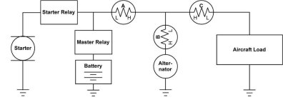
Terry, where is your shunt located, in position A or B or C in this drawing from a Dynon manual?View attachment 62593
If the shunt is placed in pos:
- A. Battery charging current. (normally positive). Recommended.
- B. Battery charging + aircraft load current. (normally positive). Recommended.
- C. Aircraft load (negative). Not recommended. Where does the current come from? Battery or Alternator?

Good luck
 
Terry, where is your shunt located, in position A or B or C in this drawing from a Dynon manual?View attachment 62593
Is this a correct diagram? Doesn't the shunt need to be on the power side? Battery + > Shunt > all of this other stuff. Every electron needs to flow through the shunt or it will not be accurate. The Alternator also needs to be on the downstream side (not battery side) or the shunt will not see the battery charging. A battery charger connected to the battery, for example, would be adding amps in and the shunt would not see it.
 
If the shunt is placed in pos:
- A. Battery charging current. (normally positive). Recommended.
- B. Battery charging + aircraft load current. (normally positive). Recommended.
- C. Aircraft load (negative). Not recommended. Where does the current come from? Battery or Alternator?

Good luck
In my current setup, it's in position C
 
In my current setup, it's in position C
The problem with the negative side is that 100% of all of your grounds need to run though the shunt. It has to be located next to the battery and be inserted before anything else. Imagine a funnel and pour water into it. Everything flows though one small stream. That is what the shunt needs. If you have anything grounded to the airframe that can get to the battery around the shunt it will cause calculation issues. This is why Garmin recommends using the positive side. It is easier to ensure that all electrons are flowing though it. People don't use the frame to send the positive. It is a lot easier to trace and troubleshoot. The negative side will work. Just make sure that it is battery to the shunt to ground. Your battery chassis ground needs to be after the shunt not before it.
 
Yes, the drawing is accurate. It has been copied right from a Dynon manual. I don't see anything wrong with it.
No matter which of the 3 shunt positions is chosen, notice that one of the shunt leads is connected to a single point.
And that point is positive. None of the shunts in that drawing are located in a negative wire.
-
Position "A" indicates if the battery is being charged or discharged.
-
Position "B" indicates how much current the alternator is putting out. Bob Nuckolls uses position "B" in his Z figures.
-
Position "C" shows how much current the aircraft electrical system is using
-
Each of the 3 positions has advantages and disadvantages. It is a matter of personal preference.
Many aircraft do not have an ammeter. A voltmeter will tell if the charging system is working or not.
If the voltage is above 13.5 or so, the battery is being charged. If the voltage is below 13, the battery is being discharged.
 
Guys, this is all very interesting, but none of it answers my original question :)

On the G3X system, with the shunt just upstream of the main buss, it there any way to get it to display as just a number without he minus sign in front of it?

I understand what the various locations have to offer, and at some point in the future I might decide to change the location to look at some different parameters, but for now, the shunt is just upstream of the buss because I wanted to see the total load on the buss.
 
So - Do you have a Shunt type sensor as delivered with Garmin engine sensor kit or a Hall Effect sensor ?
I surmise the sensor is installed to measure either battery discharge or battery charge (as opposed to a load meter install).
Does the meter show positive when engine running & battery charging ?
The more info you share the better....
I included an excerpt from G3x install re ammeter sensors & installs
Your swapping shunt leads "should" have worked if it was indeed a shunt.
Good luck.
I say again - swapping the two wires from the shunt should have changed the polarity... either at the shunt (two screw terminals), at the G3x instrumentation LRU connector or at your two inline fuses. My previous comment re polaity removed, polarity is up to the designer.
 
Last edited:
Quoted from "G3X Installation Manual - Engine/Airframe Sensor Installation Rev. W Page 21-24".
"If the ammeter readings are shown with the opposite polarity, check to see if the sense wire connections are reversed."